Nissan Qashqai J11. Manual - part 511
EC9-200
< DTC/CIRCUIT DIAGNOSIS >
[R9M]
P0106 TC BOOST SENSOR
5.
CHECK TURBOCHARGER BOOST SENSOR
Check turbocharger boost sensor. Refer to
EC9-200, "Component Inspection (Turbocharger Boost Sensor)"
.
Is the inspection result normal?
YES
>> GO TO 6.
NO
>> Replace error-detected parts.
6.
CHECK TURBOCHARGER BOOST SENSOR POWER SUPPLY CIRCUIT
1.
Turn ignition switch OFF.
2.
Check the power supply of the turbocharger boost sensor.
Is the inspection result normal?
YES
>> GO TO 7.
NO
>> Perform trouble diagnosis for power supply circuit.
7.
CHECK TURBOCHARGER BOOST SENSOR CIRCUIT FOR OPEN AND SHORT
Check turbocharger boost sensor circuit for open and short.
Is the inspection result normal?
YES
>> Check intermittent incident. Refer to
GI-41, "Intermittent Incident"
.
NO
>> Repair or replace error-detected parts.
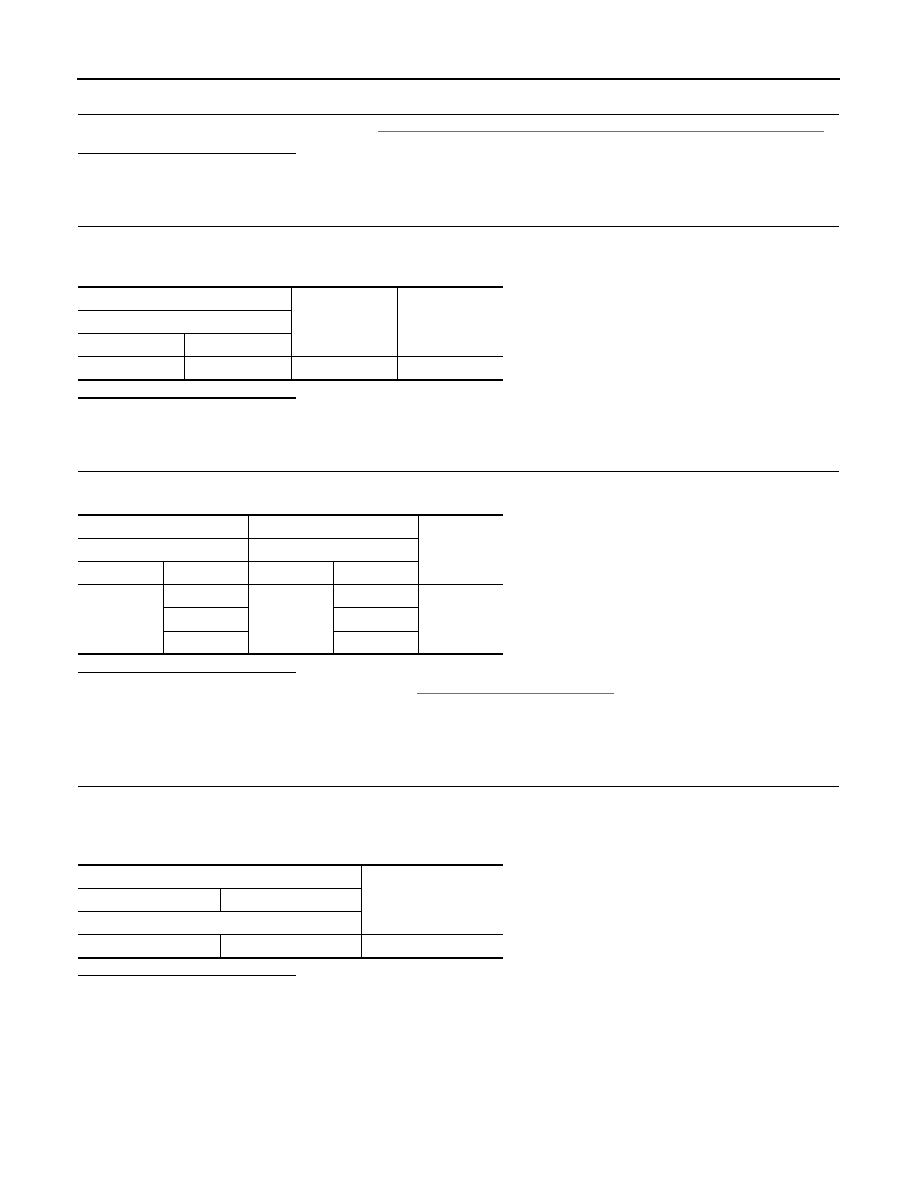
Component Inspection (Turbocharger Boost Sensor)
INFOID:0000000010309115
1.
CHECK TURBOCHARGER BOOST SENSOR
1.
Turn ignition switch OFF.
2.
Disconnect turbocharger boost sensor harness connector.
3.
Check resistance between turbocharger boost sensor terminals under the following conditions.
Is the inspection result normal?
YES
>> INSPECTION END
NO
>> Replace turbocharger boost sensor.
+
-
Voltage
(Approx.)
Turbocharger boost sensor
Connector
Terminal
F121
3
Ground
5.0 V
+
-
Continuity
ECM
Turbocharger boost sensor
Connector
Terminal
Connector
Terminal
F82
59
F121
3
Existed
81
1
85
4
Turbocharger boost sensor
Resistance
+
-
Terminal
4
1
More than 50 k
Ω