Nissan Qashqai J11. Manual - part 447


  Index      Nissan     Nissan Qashqai J11 - Service and Repair Manual


Search            


Content   ..  445  446  447  448   ..


Nissan Qashqai J11. Manual - part 447


ECK-348

< DTC/CIRCUIT DIAGNOSIS >

[K9K]

P1655 ENGINE RESTART BYPASS RELAY

P1655 ENGINE RESTART BYPASS RELAY

DTC Logic

INFOID:0000000010290005

DTC DETECTION LOGIC

DTC CONFIRMATION PROCEDURE

1.

PRECONDITIONING

If the other DTC Confirmation Procedure is performed right before this procedure, the ignition switch must be
turned OFF and wait for 10 seconds or more to start this procedure.

>> GO TO 2.

2.

PERFORM DTC CONFIRMATION PROCEDURE

With CONSULT

1.

Start the engine and warm it up to normal operating temperature.

2.

Press start/stop OFF switch and check that the switch indicator is ON.

3.

Select “AUTO STOP START” in “ACTIVE TEST” mode of “ENGINE” using CONSULT.

4.

Touch “START” and operate stop/start system. (engine stop.)

5.

Touch “CANCEL” and restart the engine.

6.

Repeat Step 3 and Step 4 twice.

Without CONSULT

1.

Activate the stop/start system. Stop the engine. Restart the engine. Refer to 

ECK-39, "STOP/START SYS-

TEM : System Description"

.

2.

Repeat Step 1 four times.

CAUTION:

Always drive vehicle at a safe speed.
Is DTC detected?

YES

>> Proceed to 

ECK-348, "Diagnosis Procedure"

.

NO

>> INSPECTION END

Diagnosis Procedure

INFOID:0000000010290006

1.

CHECK FUSE

1.

Turn ignition switch OFF.

2.

Check that the following fuse is not fusing.

Is the fuse fusing?

YES

>> Replace the fuse after repairing the applicable circuit.

NO

>> GO TO 2.

2.

CHECK ENGINE RESTART BYPASS CONTROL RELAY POWER SUPPLY

1.

Turn ignition switch OFF.

2.

Remove engine restart bypass control relay.

3.

Turn ignition switch ON.
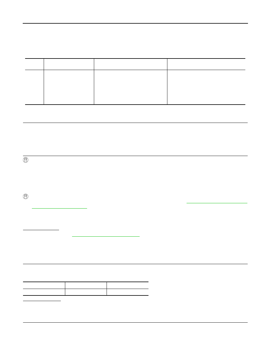
DTC

CONSULT screen terms

(Trouble diagnosis content)

DTC detecting condition

Possible cause

P1655

ENGINE RESTART BY-
PASS RELAY
(Engine restart bypass re-
lay)

At an engine restart by stop/start system, 
the voltage drop allowance is less than Ap-
prox. 0.1 V when the engine restart bypass 
relay becomes closed from the open sta-
tus, and this condition is repeated three 
times in a row.

• Harness or connectors

(Engine restart bypass relay circuit is open 
or shorted.)
(Engine restart bypass control relay circuit 
is open or shorted.)

• Engine restart bypass relay
• Engine restart bypass control relay

Location

Fuse No.

Capacity

Fuse block (J/B)

7

20 A

P1655 ENGINE RESTART BYPASS RELAY

ECK-349

< DTC/CIRCUIT DIAGNOSIS >

[K9K]

C

D

E

F

G

H

I

J

K

L

M

A

ECK

N

P

O

4.

Check the voltage between engine restart bypass control relay harness connector and ground.

Is the inspection result normal?

YES

>> GO TO 3.

NO

>> Perform the trouble diagnosis for power supply circuit.

3.

CHECK ENGINE RESTART BYPASS CONTROL RELAY CIRCUIT-1

1.

Turn ignition switch OFF.

2.

Disconnect ECM harness connector.

3.

Check the continuity between engine restart bypass control relay harness connector and ECM harness
connector.

4.

Also check harness for short to ground and to power.

Is the inspection result normal?

YES

>> GO TO 4.

NO

>> Repair or replace error-detected parts.

4.

CHECK ENGINE RESTART BYPASS CONTROL RELAY CIRCUIT-2

1.

Disconnect engine restart bypass relay harness connector.

2.

Check the continuity between engine restart bypass control relay harness connector and engine restart
bypass relay harness connector.

3.

Also check harness for short to ground and to power.

Is the inspection result normal?

YES

>> GO TO 5.

NO

>> Repair or replace error-detected parts.

5.

CHECK ENGINE RESTART BYPASS CONTROL RELAY

Check the engine restart bypass control relay. Refer to 

ECK-350, "Component Inspection (Engine Restart

Bypass Control Relay)"

Is the inspection result normal?

YES

>> GO TO 6.

NO

>> Replace error-detected parts.

6.

CHECK ENGINE RESTART BYPASS RELAY

Check the engine restart bypass relay. Refer to 

ECK-350, "Component Inspection (Engine Restart Bypass

Relay)"

.

Is the inspection result normal?

+

Voltage

Engine restart bypass control relay

Connector

Terminal

F98

1

Ground

Battery voltage

5

+

Continuity

Engine restart bypass con-

trol relay

ECM

Connector

Terminal

Connector

Terminal

F98

2

F80

55

Existed

+

Continuity

Engine restart bypass con-

trol relay

Engine restart bypass relay

Connector

Terminal

Connector

Terminal

F98

3

F146

1

Existed

ECK-350

< DTC/CIRCUIT DIAGNOSIS >

[K9K]

P1655 ENGINE RESTART BYPASS RELAY

YES

>> Check intermittent incident. Refer to 

GI-41, "Intermittent Incident"

.

NO

>> Replace error-detected parts.

Component Inspection (Engine Restart Bypass Control Relay)

INFOID:0000000010290007

1.

CHECK ENGINE RESTART BYPASS CONTROL RELAY

1.

Turn ignition switch OFF.

2.

Remove engine restart bypass control relay.

3.

Check continuity between engine restart bypass control relay
terminals as per the following condition. 

Is the inspection result normal?

YES

>> INSPECTION END

NO

>> Replace engine restart bypass control relay.

Component Inspection (Engine Restart Bypass Relay)

INFOID:0000000010290008

1.

CHECK ENGINE RESTART BYPASS RELAY-1

1.

Turn ignition switch OFF.

2.

Disconnect battery cable from negative terminal.

3.

Remove engine restart bypass relay. Refer to 

ECK-403, "Removal and Installation"

.

4.

Check the continuity between engine restart bypass relay termi-
nal and engine restart bypass relay body.

Is the inspection result normal?

YES

>> GO TO 2.

NO

>> Replace engine restart bypass relay. Refer to 

ECK-403, "Removal and Installation"

.

2.

CHECK ENGINE RESTART BYPASS RELAY-2

Check the resistance between engine restart bypass relay terminals
as per the following conditions. 

Is the inspection result normal?

YES

>> INSPECTION END

NO

>> Replace engine restart bypass relay. Refer to 

ECK-403, "Removal and Installation"

.

Engine restart bypass control relay

Condition

Continuity

+

Terminal

3

5

12 V direct current supply 
between terminals 1 and 2

Existed

No current supply

Not existed

JSBIA0671ZZ

+

Continuity

Engine restart bypass 

relay

Terminal

1

Engine restart bypass 

relay body

Existed

JSBIA1735ZZ

Engine restart bypass relay

Condition

Resistance

(Approx.)

+

Terminal

2

3

12 V direct current sup-
ply between terminal 1 
and body

10 m

No current supply

JSBIA1736ZZ

P1656 ENGINE RESTART BYPASS RELAY

ECK-351

< DTC/CIRCUIT DIAGNOSIS >

[K9K]

C

D

E

F

G

H

I

J

K

L

M

A

ECK

N

P

O

P1656 ENGINE RESTART BYPASS RELAY

DTC Logic

INFOID:0000000010290009

DTC DETECTION LOGIC

DTC CONFIRMATION PROCEDURE

1.

PRECONDITIONING

If the other DTC Confirmation Procedure is performed right before this procedure, the ignition switch must be
turned OFF and wait for 10 seconds or more to start this procedure.

>> GO TO 2.

2.

PERFORM DTC CONFIRMATION PROCEDURE

With CONSULT

1.

Start the engine and warm it up to normal operating temperature.

2.

Press start/stop OFF switch and check that the switch indicator is ON.

3.

Select “AUTO STOP START” in “ACTIVE TEST” mode of “ENGINE” using CONSULT.

4.

Touch “START” and operate stop/start system. (engine stop.)

5.

Touch “CANCEL” and restart the engine.

6.

Repeat Step 3 and Step 4 twice.

Without CONSULT

1.

Activate the stop/start system. Stop the engine. Restart the engine. Refer to 

ECK-39, "STOP/START SYS-

TEM : System Description"

.

2.

Repeat Step 1 four times.

CAUTION:

Always drive vehicle at a safe speed.
Is DTC detected?

YES

>> Proceed to 

ECK-352, "Diagnosis Procedure"

.

NO

>> INSPECTION END

Diagnosis Procedure

INFOID:0000000010516037

1.

CHECK FUSE

1.

Turn ignition switch OFF.

2.

Check that the following fuse is not fusing.

Is the fuse fusing?

YES

>> Replace the fuse after repairing the applicable circuit.

NO

>> GO TO 2.

2.

CHECK ENGINE RESTART BYPASS CONTROL RELAY POWER SUPPLY

DTC

CONSULT screen terms

(Trouble diagnosis content)

DTC detecting condition

Possible cause

P1656


(—)
• 1.DEF: INVALID 

SOURCE COMPUTER 
MULTIPLEX SIGNALS

• 2.DEF: INVALID 

SOURCE COMPUTER 
MULTIPLEX SIGNALS

• 3.DEF: IMPLAUSIBLE 

SIGNAL

At an engine restart by stop/start system, 
the voltage right after the starter motor ac-
tivation is less than Approx. 8 V.

• Harness and connectors

(Engine restart bypass relay circuit is open 
or shorted.)
(Engine restart bypass control relay circuit 
is open or shorted.)

• Engine restart bypass relay
• Engine restart bypass control relay

Location

Fuse No.

Capacity

Fuse block (J/B)

7

20 A


Content   ..  445  446  447  448   ..