Nissan Qashqai J11. Manual - part 442
ECK-328
< DTC/CIRCUIT DIAGNOSIS >
[K9K]
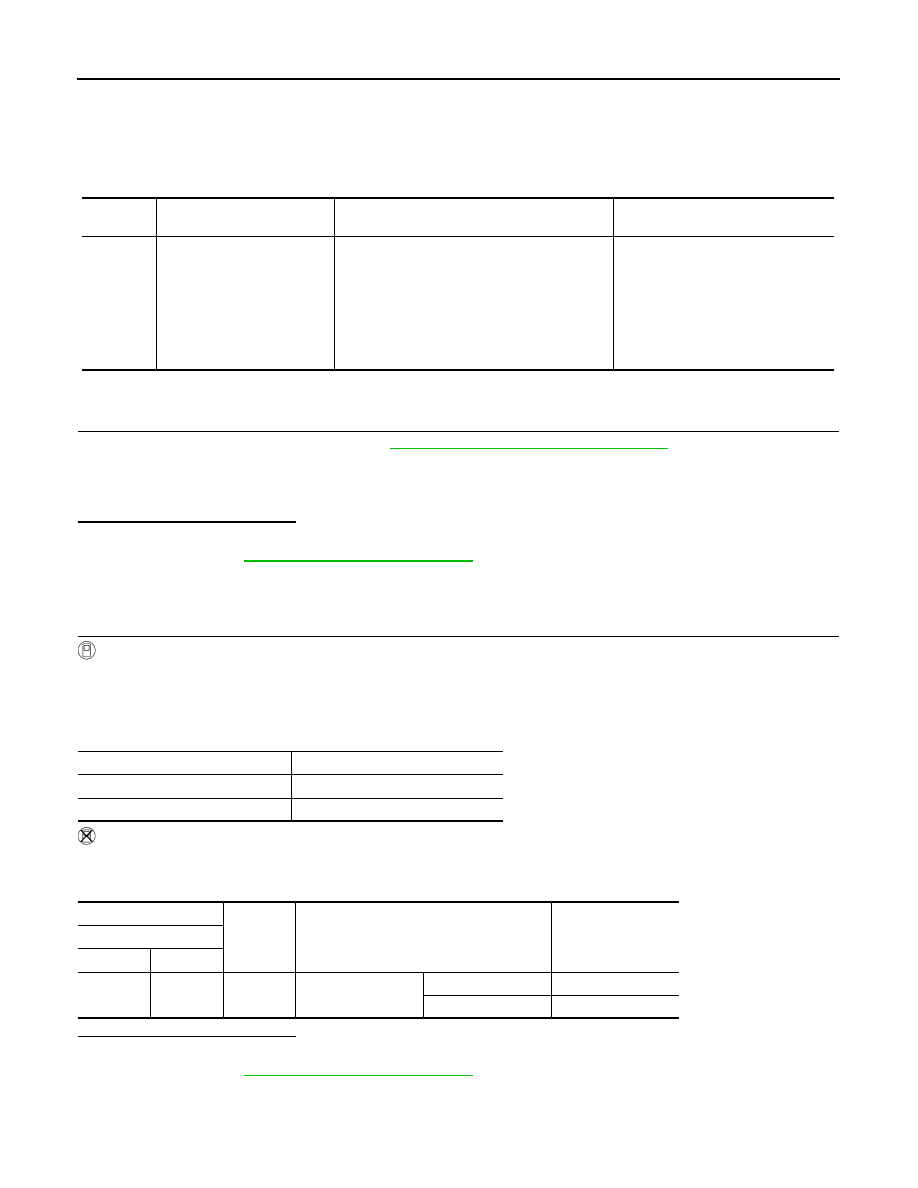
P1589 NEUTRAL SWITCH
P1589 NEUTRAL SWITCH
DTC Logic
INFOID:0000000010434281
DTC DETECTION LOGIC
DTC CONFIRMATION PROCEDURE
1.
PERFORM COMPONENT FUNCTION CHECK
Perform component function check. Refer to
ECK-328, "Component Function Check"
NOTE:
Use Component Function Check the overall function of the neutral position switch circuit. During this check,
the DTC might not be confirmed.
Is the inspection result normal?
YES
>> INSPECTION END
NO
>> Proceed to
ECK-329, "Diagnosis Procedure"
Component Function Check
INFOID:0000000010514760
1.
PERFORM COMPONENT FUNCTION CHECK
With CONSULT
1.
Turn ignition switch ON.
2.
Select “MANUAL GEARBOX LEVER IN NEUTRAL” in “DATA MONITOR” mode of “ENIGNE” using CON-
SULT.
3.
Check the “MANUAL GEARBOX LEVER IN NEUTRAL” indication as per the following conditions.
Without CONSULT
1.
Turn ignition switch ON.
2.
Check the voltage between ECM harness connectors as per the following conditions.
Is the inspection result normal?
YES
>> INSPECTION END
NO
>> Proceed to
ECK-329, "Diagnosis Procedure"
DTC No.
CONSULT screen terms
(Trouble diagnosis content)
DTC detecting condition
Possible cause
P1589
NEUTRAL POSITION SW/
SENSOR
(Neutral position switch/sen-
sor)
• 1.DEF: SIGNAL INCO-
HERENCE
• 2.DEF:IMPLAUSIBLE SIG-
NAL
Neutral position switch signal remains ON for a
long driving distance.
• Harness and connectors
(Neutral position switch circuit is
shorted.)
• Neutral position switch
Selector lever position
Indication
Neutral position
DETECTED
Except above position
NOT DETECTED
+
−
Condition
Voltage
(Approx.)
ECM
Connector
Terminal
F81
117
Ground
Shift lever
Neutral
Battery voltage
Except above
0 V