Nissan Qashqai J11. Manual - part 379


  Index      Nissan     Nissan Qashqai J11 - Service and Repair Manual


Search            


Content   ..  377  378  379  380   ..


Nissan Qashqai J11. Manual - part 379


ECK-76

< ECU DIAGNOSIS INFORMATION >

[K9K]

ECM

ECU DIAGNOSIS INFORMATION

ECM

Reference Value

INFOID:0000000010289668
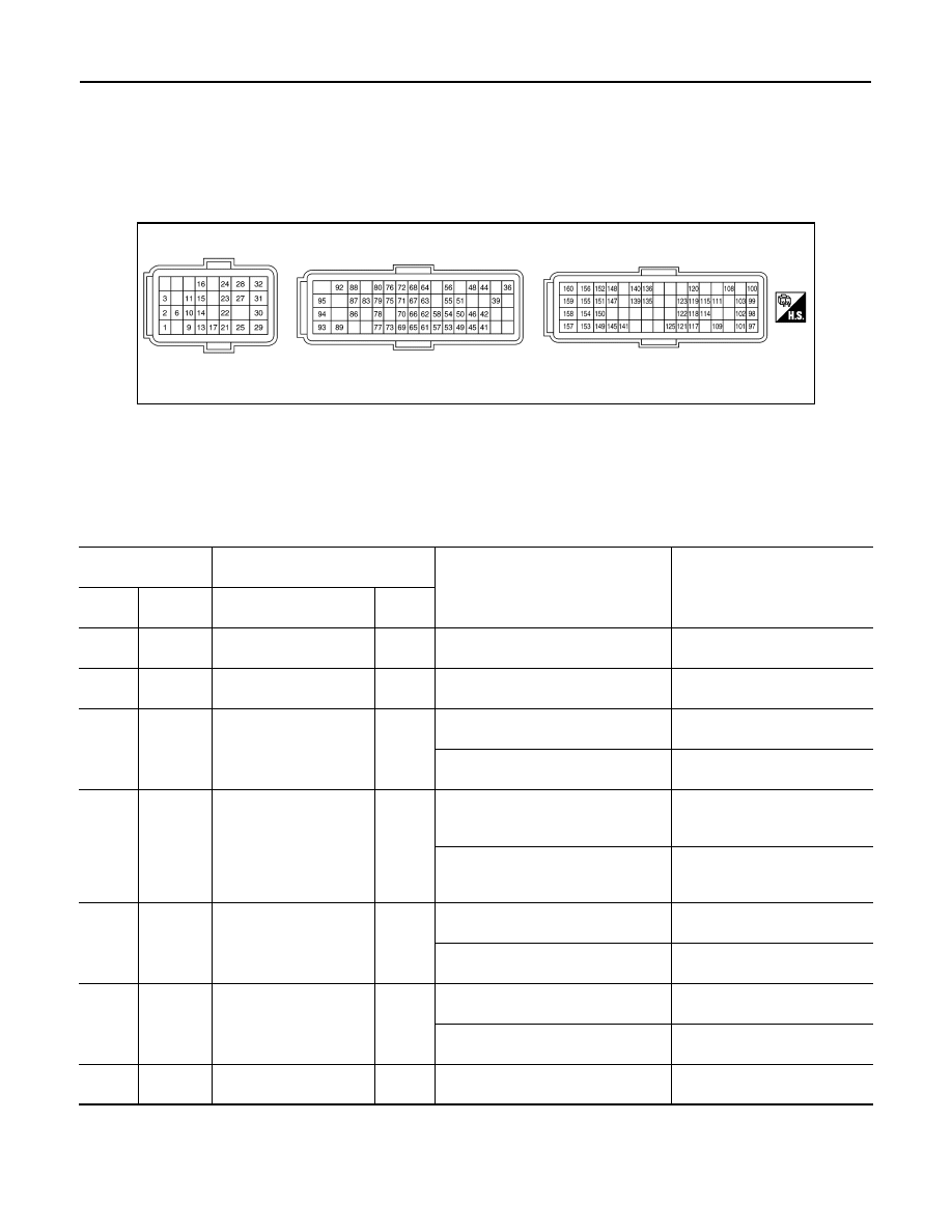
TERMINAL LAYOUT

PHYSICAL VALUES

NOTE:
• ECM is located in the engine room left side near battery.
• Pulse signal is measured by CONSULT.

JSBIA5035GB

Terminal No.

(Wire color)

Description

Condition

Value

(Approx.)

+

Signal name

Input/

Output

1

(L)

CAN communication line
(CAN-H)

Input/

Output

2

(P)

CAN communication line
(CAN-L)

Input/

Output

3

(SB)

29

(B)

ASCD MAIN switch

Input

[Ignition switch: ON]
ASCD MAIN switch: OFF

0 V

[Ignition switch: ON]
ASCD MAIN switch: ON

Battery voltage

(11 - 14 V)

6

(V)

29

(B)

Clutch interlock switch

Input

[Ignition switch: ON]
• Engine stopped
• Clutch pedal: Fully released

0 V

[Ignition switch: ON]
• Engine stopped
• Clutch pedal: Fully depressed

BATTERY VOLTAGE

(11 - 14 V)

9

(R)

29

(B)

Clutch pedal position 
switch

Input

[Ignition switch: ON]
• Clutch pedal: Fully released

0 V

[Ignition switch: ON]
• Clutch pedal: Fully depressed

11.25 V

10

(V)

29

(B)

Speed limiter MAIN 
switch

Input

[Ignition switch: ON]
Speed limiter MAIN switch: OFF

0 V

[Ignition switch: ON]
Speed limiter MAIN switch: ON

Battery voltage

(11 - 14 V)

11

(G)

29

(B)

Fuel pump control module
(Diagnosis)

Input

[Ignition switch: ON]

11.0 V

ECM

ECK-77

< ECU DIAGNOSIS INFORMATION >

[K9K]

C

D

E

F

G

H

I

J

K

L

M

A

ECK

N

P

O

13

(BR)

29

(B)

Fuel pump control module
(Command)

Output

[Ignition switch: ON]
Fuel pump not activates

0.05 V

(PWM duty: less than 14%)

[Ignition switch: ON]
Fuel pump activated

0 – 6.74 V

(PWM duty: Approx. 40%)

Engine running at idle

PWM duty: 50 – 60%

14

(BR)

Sensor ground
(ASCD steering switch)

15

(G)

14

(BR)

ASCD steering switch

Input

[Ignition switch: ON]
• ASCD steering switch: OFF

4 V

[Ignition switch: ON]
• CANCEL switch: Pressed

1 V

[Ignition switch: ON]
• RES/+ switch: Pressed

3 V

[Ignition switch: ON]
• SET/

 switch: Pressed

2 V

16

(LG)

29

(B)

Ignition switch

Input

[Ignition switch: ON]

12.20 V

17

(BG)

29

(B)

Stop lamp switch

Input

[Ignition switch: OFF]
• Brake pedal: Fully released

0 V

[Ignition switch: OFF]
• Brake pedal: Slightly depressed

12.18 V

21

(Y)

Sensor ground
(Accelerator pedal posi-
tion sensor 2)

22

(W)

21

(Y)

Accelerator pedal posi-
tion sensor 2

Input

[Ignition switch: ON]
• Engine stopped
• Accelerator pedal: Fully released

[Ignition switch: ON]
• Engine stopped
• Accelerator pedal: Fully depressed

23

(BG)

21

(Y)

Sensor power supply
(Accelerator pedal posi-
tion sensor 2)

[Ignition switch: ON]

5 V

24

(L)

29

(B)

Fuel heater and water in 
fuel sensor

Input

[Engine is running]
• Warm-up condition
• Idle speed

14.0 V

25

(B)

ECM ground

26

(B)

ECM ground

Terminal No.

(Wire color)

Description

Condition

Value

(Approx.)

+

Signal name

Input/

Output

JSBIA4811ZZ

JSBIA4812ZZ

ECK-78

< ECU DIAGNOSIS INFORMATION >

[K9K]

ECM

27

(V)

30

(GR)

Sensor power supply
(Accelerator pedal posi-
tion sensor 1)

[Ignition switch: ON]

5 V

29

(B)

ECM ground

30

(GR)

Sensor ground
(Accelerator pedal posi-
tion sensor 1)

31

(R)

30

(GR)

Accelerator pedal posi-
tion sensor 1

Input

[Ignition switch: ON]
• Engine stopped
• Accelerator pedal: Fully released

[Ignition switch: ON]
• Engine stopped
• Accelerator pedal: Fully depressed

32

(B)

ECM ground

36

(G)

29

(B)

ECM relay
(Self shut-off)

Output

[Engine is running]
[Ignition switch: OFF]
• A few seconds after turning ignition 

switch OFF

0.78 V

[Ignition switch: OFF]
• More than a few seconds after turn-

ing ignition switch OFF

12.42 V

39

(BR)

29

(B)

Water heater 2

Output

Diesel particulate filter regeneration 
mode

0 V

Diesel particulate filter No regenera-
tion mode

13.67 V

41

(P)

50

(V)

Sensor power supply
(Camshaft position sen-
sor)

[Ignition switch: ON]

5 V

Terminal No.

(Wire color)

Description

Condition

Value

(Approx.)

+

Signal name

Input/

Output

JSBIA4784ZZ

JSBIA4785ZZ

ECM

ECK-79

< ECU DIAGNOSIS INFORMATION >

[K9K]

C

D

E

F

G

H

I

J

K

L

M

A

ECK

N

P

O

42

(Y)

50

(V)

Camshaft position sensor 

Input

[Engine is running]
• Warm-up condition
• Idle speed

NOTE:
The pulse cycle changes depending 
on rpm at idle

[Engine is running]
• Engine speed is 2,000 rpm

44

(BG)

29

(B)

Water heater 1

Output

Diesel particulate filter regeneration 
mode

0 V

Diesel particulate filter No regenera-
tion mode

14.23 V

45

(L)

68

(B)

Sensor power supply
(Fuel rail pressure sen-
sor)

[Ignition switch: ON]

5.0 V

46

(GR)

86

(G)

Mass air flow sensor

Input

[Engine is running]
• Warm-up condition
• Idle speed

[Engine is running]
• Warm-up condition
• Engine speed: 2,500 rpm

48

(Y)

29

(B)

Engine restart relay con-
trol signal

Output

[Stop/start system operates]
• While cranking of restart

11.76 V

(While operating the starter mo-

tor)

[Engine is running]
• Warm-up condition
• Idle speed

14.46 V

49

(L)

54

(SB)

Sensor power supply
(Low fuel rail pressure 
sensor)

[Ignition switch: ON]

5.0 V

50

(V)

Sensor ground
(Camshaft position sen-
sor)

Terminal No.

(Wire color)

Description

Condition

Value

(Approx.)

+

Signal name

Input/

Output

JSBIA4786ZZ

JSBIA4787ZZ

JSBIA4788ZZ

JSBIA4789ZZ


Content   ..  377  378  379  380   ..