Nissan Qashqai J11. Manual - part 304
P0117, P0118 ECT SENSOR
ECM-193
< DTC/CIRCUIT DIAGNOSIS >
[MR20DD]
C
D
E
F
G
H
I
J
K
L
M
A
ECM
N
P
O
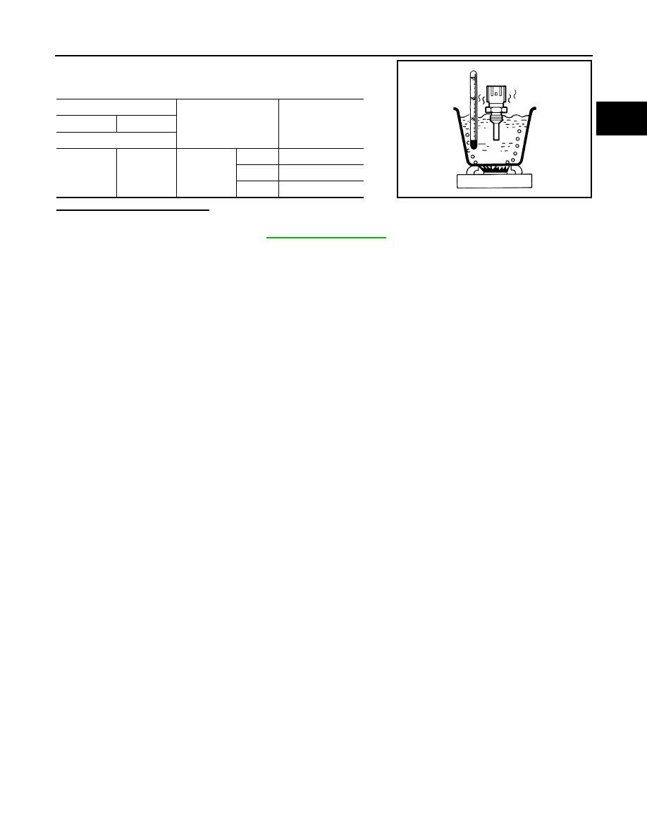
4.
Check resistance between engine coolant temperature sensor
terminals by heating with hot water as shown in the figure.
Is the inspection result normal?
YES
>> INSPECTION END
NO
>> Replace ECT sensor. Refer to
ECT sensor
Condition
Resistance
+
−
Terminal
1
2
Tempera-
ture [
°
C (
°
F)]
20 (68)
2.37 - 2.63 k
Ω
50 (122)
0.68 - 1.00 k
Ω
90 (194)
0.236 - 0.260 k
Ω
JMBIA0080ZZ