Nissan Qashqai J11. Manual - part 263


  Index      Nissan     Nissan Qashqai J11 - Service and Repair Manual


Search            


Content   ..  261  262  263  264   ..


Nissan Qashqai J11. Manual - part 263


STRUCTURE AND OPERATION

ECM-29

< SYSTEM DESCRIPTION >

[MR20DD]

C

D

E

F

G

H

I

J

K

L

M

A

ECM

N

P

O

STRUCTURE AND OPERATION

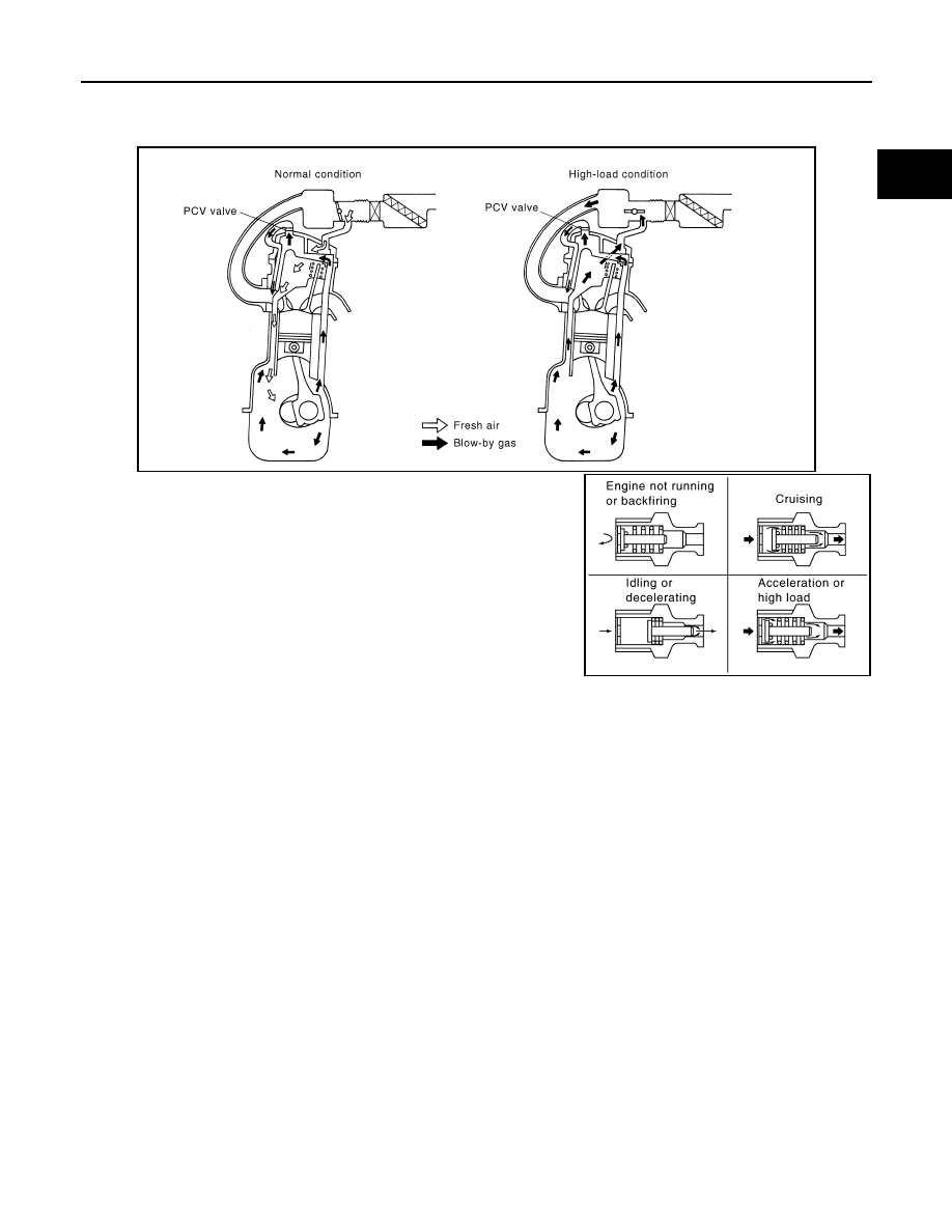
Positive Crankcase Ventilation

INFOID:0000000010702814

This system returns blow-by gas to the intake manifold.The positive
crankcase ventilation (PCV) valve is provided to conduct crankcase
blow-by gas to the intakemanifold.
During partial throttle operation of the engine, the intake manifold
sucks the blow-by gas through the PCV valve.
Normally, the capacity of the valve is sufficient to handle any blow-by
and a small amount of ventilating air.The ventilating air is drawn from
the air inlet tubes into the crankcase. In this process the air passes
throughthe hose connecting air inlet tubes to rocker cover. Under
full-throttle condition, the manifold vacuum is insufficient to draw the
blow-by flow through the valve.The flow goes through the hose con-
nection in the reverse direction.

PBIB2962E

PBIB1588E

ECM-30

< SYSTEM DESCRIPTION >

[MR20DD]

SYSTEM

SYSTEM

ENGINE CONTROL SYSTEM

ENGINE CONTROL SYSTEM : System Description

INFOID:0000000010702815

SYSTEM DIAGRAM

SYSTEM DESCRIPTION

JSBIA5005GB

SYSTEM

ECM-31

< SYSTEM DESCRIPTION >

[MR20DD]

C

D

E

F

G

H

I

J

K

L

M

A

ECM

N

P

O

• The adopted system enables comprehensive engine control. ECM (engine control module) performs various

controls such as fuel injection control, ignition timing control, idling engine speed control, EVAP purge con-
trol and etc., and this system communicates with control unit such as CVT, ABS, etc. via CAN communica-
tion line.

• The adopted diagnostic system corresponding to OBD (on board diagnostic) system enables various func-

tion check and easily malfunction diagnosis in the engine control system.

ENGINE CONTROL SYSTEM : Fail-safe

INFOID:0000000010702816

NON DTC RELATED ITEM

DTC RELATED ITEM

Description

Function

Reference

Fuel injection control

ECM-35, "DIG (DIRECT INJECTION GASOLINE) SYSTEM : 
System Description"

Fuel pressure control

ECM-38, "FUEL PRESSURE CONTROL : System Descrip-
tion"

Electric ignition control

ECM-39, "ELECTRIC IGNITION SYSTEM : System Descrip-
tion"

Idling control 

ECM-40, "IDLE SPEED CONTROL : System Description"

Cooling fan control

ECM-41, "COOLING FAN CONTROL : System Description"

Intake valve timing control

ECM-42, "INTAKE VALVE TIMING CONTROL : System De-
scription"

Exhaust valve timing control

ECM-43, "EXHAUST VALVE TIMING CONTROL : System 
Description"

Intake manifold runner control valve control

ECM-45, "INTAKE MANIFOLD RUNNER CONTROL : Sys-
tem Description"

Engine protection control (Low engine oil pressure)

ECM-46, "ENGINE PROTECTION CONTROL AT LOW EN-
GINE OIL PRESSURE : System Description"

Air conditioning cut control

ECM-47, "AIR CONDITIONING CUT CONTROL : System De-
scription"

ASCD (Automatic speed control device)

ECM-48, "AUTOMATIC SPEED CONTROL DEVICE (ASCD) 
: System Description"

ECO mode control

ECM-50, "ECO MODE SYSTEM : System Description"

Engine/CVT/ABS total control

ECM-50, "INTEGRATED CONTROL OF ENGINE, CVT, AND 
ABS : System Description"

EVAP purge control

ECM-51, "EVAPORATIVE EMISSION SYSTEM : System De-
scription"

Power generation voltage variable control

ECM-51, "POWER GENERATION VOLTAGE VARIABLE 
CONTROL SYSTEM : System Description"

Fail-safe function

ECM-87, "Fail-safe"

On board diagnostic (OBD) system

ECM-55, "Diagnosis Description"

Detected 

items

Engine operating condition in 

fail-safe mode

Remarks

Malfunction 
indicator lamp 
circuit

Engine speed will not rise more 
than 2,500 rpm due to the fuel 
cut

When there is an open circuit on MIL circuit, the ECM cannot warn the driver by 
lighting up MIL when there is malfunction on engine control system.
Therefore, when electrical controlled throttle and part of ECM related diagnoses are 
continuously detected as NG for 5 trips, ECM warns the driver that engine control 
system malfunctions and MIL circuit is open by means of operating fail safe func-
tion.
The fail safe function also operates when above diagnoses except MIL circuit are 
detected and demands the driver to repair the malfunction.

ECM-32

< SYSTEM DESCRIPTION >

[MR20DD]

SYSTEM

When a DTC is detected, ECM executes a mode (in the Fail-safe mode) applicable to the DTC. The fail-safe
mode has the preset traveling control mode (accelerator angle variation and engine output limit), device fix
mode and combustion control mode.

Fail Safe Pattern

Fail Safe List

×

:Applicable —: Not applicable

Fail safe mode

Vehicle behavior

Traveling con-
trol mode

Accelerator an-
gle variation 
control

ECM controls the accelerator pedal depression speed to make it slower than actual speed. This 
causes a drop in accelerating performance and encourages the driver to repair malfunction.
NOTE:
ECM does not control the accelerator pedal releasing speed.

Engine output 
control

ECM reduces the engine output, according to the rise in engine speed. This reduces the vehicle 
speed to encourage the driver to repair malfunction.

Device fix mode

• This mode fixes the IVT control solenoid valve and the EVT control solenoid valve in the refer-

ence position.

• The intake manifold runner control valve motor is turned OFF (intake manifold runner control 

valve opens).

Combustion 
control mode

Stratified charge 
combustion 
control at start-
ing

No stratified charge combustion at starting (cold start).

Idle speed con-
trol

Stops feedback control of idle speed and controls with specified speed.

Recovery speed 
control at decel-
erating

Stops recovery speed control by the fuel cut at decelerating and controls with specified speed.

Idle neutral con-
trol

Stops idle neutral control.

Ignition timing 
correction con-
trol

Partially controls ignition timing control.

Retardation 
control

Controls ignition timing delay control in the intermediate water temperature range.

Pattern

Fail safe mode

A

Traveling control mode

Accelerator angle variation control

B

Engine output control

C

Device fix mode

D

Combustion control mode

Stratified charge combustion control at starting

E

• Idle speed control
• Recovery speed control at decelerating
• Idle neutral control

F

• Ignition timing correction control
• Retardation control

DTC No.

Detected items

Vehicle behavior

Pattern

Others

A

B

C

D

E

F

P0011

Intake valve timing control

×

P0014

Exhaust valve timing control

×

P0075

Intake valve timing control sole-
noid valve

×

P0078

Exhaust valve timing control so-
lenoid valve

×


Content   ..  261  262  263  264   ..