Nissan Qashqai J11. Manual - part 258


  Index      Nissan     Nissan Qashqai J11 - Service and Repair Manual


Search            


Content   ..  256  257  258  259   ..


Nissan Qashqai J11. Manual - part 258


PRECAUTIONS

ECM-9

< PRECAUTION >

[MR20DD]

C

D

E

F

G

H

I

J

K

L

M

A

ECM

N

P

O

On Board Diagnostic (OBD) System of Engine and CVT

INFOID:0000000010702780

The ECM has an on board diagnostic system. It will light up the malfunction indicator lamp (MIL) to warn the
driver of a malfunction causing emission deterioration.

CAUTION:

• Be sure to turn the ignition switch OFF and disconnect the negative battery cable before any repair

or inspection work. The open/short circuit of related switches, sensors, solenoid valves, etc. will
cause the MIL to light up.

• Be sure to connect and lock the connectors securely after work. A loose (unlocked) connector will

cause the MIL to light up due to the open circuit. (Be sure the connector is free from water, grease,
dirt, bent terminals, etc.)

• Certain systems and components, especially those related to OBD, may use a new style slide-lock-

ing type harness connector. For description and how to disconnect, refer to 

PG-5, "Harness Connec-

tor"

.

• Be sure to route and secure the harnesses properly after work. The interference of the harness with

a bracket, etc. may cause the MIL to light up due to the short circuit.

• Be sure to connect rubber tubes properly after work. A misconnected or disconnected rubber tube

may cause the MIL to light up due to the malfunction of the EVAP system or fuel injection system,
etc.

• Be sure to erase the unnecessary malfunction information (repairs completed) from the ECM and

TCM (Transmission control module) before returning the vehicle to the customer.

General Precautions

INFOID:0000000010702781

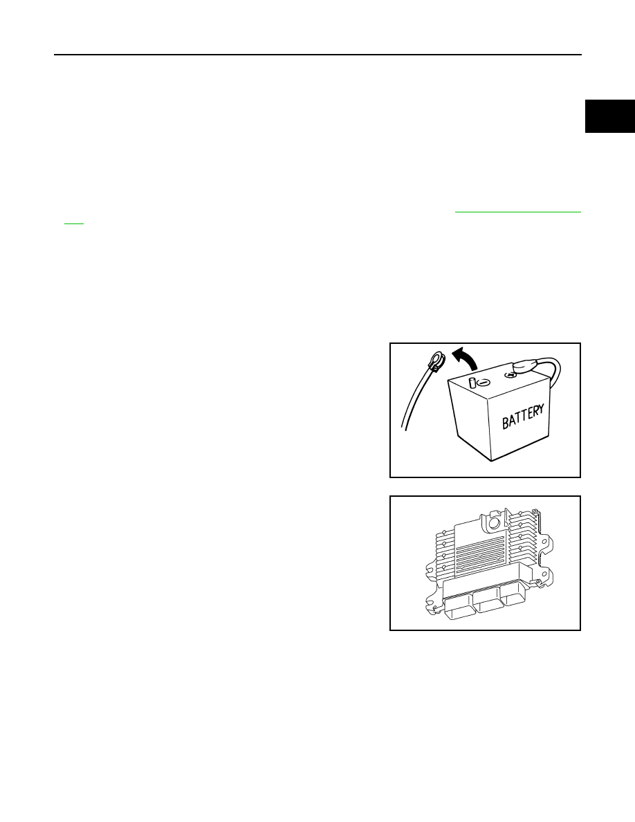
• Always use a 12 volt battery as power source.
• Do not attempt to disconnect battery cables while engine is

running.

• Before connecting or disconnecting the ECM harness con-

nector, turn ignition switch OFF and disconnect negative bat-
tery cable. Failure to do so may damage the ECM because
battery voltage is applied to ECM even if ignition switch is
turned OFF.

• Before removing parts, turn ignition switch OFF and then dis-

connect battery ground cable.

• Do not disassemble ECM.
• If a battery cable is disconnected, the memory will return to

the ECM value.
The ECM will now start to self-control at its initial value.
Engine operation can vary slightly when the terminal is dis-
connected. However, this is not an indication of a malfunc-
tion. Do not replace parts because of a slight variation.

• If the battery is disconnected, the following emission-related

diagnostic information will be lost within 24 hours.

Diagnostic trouble codes
1st trip diagnostic trouble codes
Freeze frame data
1st trip freeze frame data
System readiness test (SRT) codes
Test values

SEF289H

JPBIA4618ZZ

ECM-10

< PRECAUTION >

[MR20DD]

PRECAUTIONS

• When connecting or disconnecting pin connectors into or

from ECM, take care not to damage pin terminals (bend or
break).
Make sure that there are not any bends or breaks on ECM pin
terminal, when connecting pin connectors.

• Securely connect ECM harness connectors.

A poor connection can cause an extremely high (surge) volt-
age to develop in coil and condenser, thus resulting in dam-
age to ICs.

• Keep engine control system harness at least 10 cm (4 in) away

from adjacent harness, to prevent engine control system mal-
functions due to receiving external noise, degraded operation
of ICs, etc.

• Keep engine control system parts and harness dry.
• Before replacing ECM, perform ECM Terminals and Reference

Value inspection and make sure ECM functions properly.
Refer to 

ECM-73, "Reference Value"

.

• Handle mass air flow sensor carefully to avoid damage.
• Do not clean mass air flow sensor with any type of detergent.
• Do not disassemble electric throttle control actuator.
• Even a slight leak in the air intake system can cause serious

incidents.

• Do not shock or jar the camshaft position sensor (PHASE),

crankshaft position sensor (POS).

• After performing each TROUBLE DIAGNOSIS, perform DTC

CONFIRMATION PROCEDURE or Component Function
Check. The DTC should not be displayed in the DTC Confir-
mation Procedure if the repair is completed. The Component
Function Check should be a good result if the repair is com-
pleted.

PBIB0090E

MEF040D

SAT652J

PRECAUTIONS

ECM-11

< PRECAUTION >

[MR20DD]

C

D

E

F

G

H

I

J

K

L

M

A

ECM

N

P

O

• When measuring ECM signals with a circuit tester, never allow

the two tester probes to contact.
Accidental contact of probes will cause a short circuit and
damage the ECM power transistor.

• Do not operate fuel pump when there is no fuel in lines.
• Tighten fuel hose clamps to the specified torque.

• Do not depress accelerator pedal when starting.
• Immediately after starting, do not rev up engine unnecessar-

ily.

• Do not rev up engine just prior to shutdown.

• When installing C.B. ham radio or a mobile phone, be sure to

observe the following as it may adversely affect electronic
control systems depending on installation location.

Keep the antenna as far as possible from the electronic con-

trol units.

Keep the antenna feeder line more than 20 cm (8 in) away

from the harness of electronic controls.
Do not let them run parallel for a long distance.

Adjust the antenna and feeder line so that the standing-wave

ratio can be kept smaller.

Be sure to ground the radio to vehicle body.

SEF348N

SEF709Y

SEF708Y

ECM-12

< PREPARATION >

[MR20DD]

PREPARATION

PREPARATION

PREPARATION

Special Service Tools

INFOID:0000000010702782

NOTE:
The actual shapes of the tools may differ from those illustrated here.

Commercial Service Tools

INFOID:0000000010702783

Tool number
(SPX-North America 
No.)
Tool name

Description

KV10120000
Fuel tube adapter

Measures fuel pressure

JSBIA0410ZZ

Tool name
(SPX-North America 
No.)

Description

Fuel pressure gauge

Measuring fuel pressure

Fuel filler cap adapter
i.e.: (MLR-8382)

Checks fuel tank vacuum relief valve opening 
pressure

Socket wrench

Removes and installs engine coolant temperature 
sensor

ZZA0061D

S-NT815

S-NT705


Content   ..  256  257  258  259   ..