Nissan Qashqai J11. Manual - part 241


  Index      Nissan     Nissan Qashqai J11 - Service and Repair Manual


Search            


Content   ..  239  240  241  242   ..


Nissan Qashqai J11. Manual - part 241


ECH-262

< DTC/CIRCUIT DIAGNOSIS >

[HRA2DDT]

P1589 PARK/NEUTRAL POSITION SWITCH

NO

>> GO TO 3.

3.

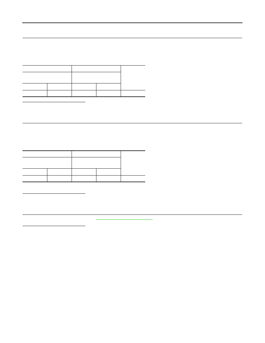
CHECK REVERSE/NEUTRAL POSITION SWITCH POWER SUPPLY CIRCUIT

1.

Turn ignition switch OFF.

2.

Disconnect IPDM E/R harness connector.

3.

Check the continuity between reverse/neutral position switch harness connector and IPDM E/R harness
connector.

Is the inspection result normal?

YES

>> Perform the trouble diagnosis for power supply circuit.

NO

>> Repair or replace error-detected parts.

4.

CHECK REVERSE/NEUTRAL POSITION INPUT SIGNAL CIRCUIT

1.

Turn ignition switch OFF.

2.

Disconnect ECM harness connector.

3.

Check the continuity between reverse/neutral position switch harness connector and ECM harness con-
nector.

4.

Also check harness for short to ground.

Is the inspection result normal?

YES

>> GO TO 5.

NO

>> Repair or replace error-detected parts.

5.

CHECK INTERMITTENT INCIDENT

Check intermittent incident. Refer to 

GI-41, "Intermittent Incident"

.

Is the inspection result normal?

YES

>> Replace reverse/neutral position switch.

NO

>> Repair or replace error-detected parts.

+

Continuity

Reverse/Neutral position 

switch

IPDM E/R

Connector

Terminal

Connector

Terminal

F100

2

F90

101

Existed

+

Continuity

Reverse/Neutral position 

switch

ECM

Connector

Terminal

Connector

Terminal

F100

3

F18

143

Existed

P158A CPP SWITCH

ECH-263

< DTC/CIRCUIT DIAGNOSIS >

[HRA2DDT]

C

D

E

F

G

H

I

J

K

L

M

A

ECH

N

P

O

P158A CPP SWITCH

DTC Logic

INFOID:0000000010500722

DTC DETECTION LOGIC

DTC CONFIRMATION PROCEDURE

1.

CONDITIONING

Turn ignition switch OFF and wait at least 12 minutes.

>> GO TO 2.

2.

PERFORM DTC CONFIRMATION PROCEDURE

1.

Start engine and let it idle.

2.

Depress the clutch pedal.

3.

Release the clutch pedal.

4.

Repeat step 2 and 3 for 10 times.

5.

Check DTC.

Is DTC detected?

YES

>> Proceed to 

ECH-263, "Diagnosis Procedure"

.

NO

>> INSPECTION END

Diagnosis Procedure

INFOID:0000000010500723

1.

.CHECK ECM HARNESS CONNECTOR CONNECTION

1.

Turn ignition switch OFF. 

2.

Check ECM harness connector connection.

Is the inspection result normal?

YES

>> GO TO 2.

NO

>> Repair or replace error-detected parts.

2.

CHECK CLUTCH PEDAL POSITION SWITCH HARNESS AND CLUTCH INTERLOCK SWITCH CONNEC-

TOR CONNECTION

Check clutch pedal position switch and clutch interlock switch harness connector connection.

Is the inspection result normal?

YES

>> GO TO 3.

NO

>> Repair or replace error-detected parts.

3.

CHECK CLUTCH PEDAL POSITION SWITCH POWER SUPPLY

1.

Turn ignition switch OFF.

2.

Disconnect clutch pedal position switch harness connector.

3.

Turn ignition switch ON.

4.

Check the voltage between clutch pedal position switch and ground.

DTC No.

CONSULT screen terms

(Trouble diagnosis content)

DTC detecting condition

Possible cause

P158A

CLUTCH SWITCH
(Clutch switch)

Correlation of two clutch pedal position 
switch signal is inconsistency.

• Harness or connectors

(Clutch pedal position switch circuit 
is shorted.)
(Clutch interlock switch circuit is 
shorted.)

• Clutch pedal position switch
• Clutch interlock switch

ECH-264

< DTC/CIRCUIT DIAGNOSIS >

[HRA2DDT]

P158A CPP SWITCH

Is the inspection result normal?

YES

>> GO TO 4.

NO

>> GO TO 6.

4.

CHECK CLUTCH PEDAL POSITION SWITCH GROUND CIRCUIT

1.

Turn ignition switch OFF.

2.

Check the continuity between clutch pedal position switch harness connector and ground.

3.

Also check harness for short to power.

Is the inspection result normal?

YES

>> GO TO 5.

NO

>> Repair or replace error-detected parts.

5.

CHECK CLUTCH PEDAL POSITION SWITCH

Refer to 

ECH-265, "Component Inspection"

.

Is the inspection result normal?

YES

>> GO TO 7.

NO

>> Repair or replace error-detected parts.

6.

CHECK CLUTCH PEDAL POSITION SWITCH INPUT SIGNAL CIRCUIT

1.

Disconnect ECM harness connector.

2.

Check the continuity between clutch pedal position switch harness connector and ECM harness connec-
tor.

3.

Also check harness for short to ground and short to power.

Is the inspection result normal?

YES

>> GO TO 7.

NO

>> Repair or replace error-detected parts.

7.

CHECK CLUTCH INTERLOCK SWITCH POWER SUPPLY

1.

Turn ignition switch OFF.

2.

Disconnect clutch interlock switch harness connector.

3.

Turn ignition switch ON.

4.

Check the voltage between clutch interlock switch and ground.

Is the inspection result normal?

YES

>> GO TO 8.

NO

>> Perform trouble diagnosis for power supply circuit.

Clutch pedal position switch

Voltage

+

Connector

Terminal

E2

1

Ground

Battery voltage

Clutch pedal position switch

Ground

Continuity

Connector

Terminal

E2

2

Ground

Existed

Clutch pedal position switch

ECM

Continuity

Connector

Terminal

Connector

Terminal

E2

1

E9

9

Existed

+

Voltage

Connector

Terminal

E52

1

Ground

Battery voltage

P158A CPP SWITCH

ECH-265

< DTC/CIRCUIT DIAGNOSIS >

[HRA2DDT]

C

D

E

F

G

H

I

J

K

L

M

A

ECH

N

P

O

8.

CHECK CLUTCH PEDAL POSITION SWITCH INPUT SIGNAL CIRCUIT

1.

Turn ignition switch OFF.

2.

Disconnect ECM harness connector.

3.

Check the continuity between clutch interlock switch harness connector and ECM harness connector.

4.

Also check harness for short to ground and short to power.

Is the inspection result normal?

YES

>> GO TO 9.

NO

>> Repair or replace error-detected parts.

9.

CHECK CLUTCH INTERLOCK SWITCH

Refer to 

ECH-265, "Component Inspection"

.

Is the inspection result normal?

YES

>> Perform intermittent incident. Refer to 

GI-41, "Intermittent Incident"

.

NO

>> Repair or replace error-detected parts.

Component Inspection

INFOID:0000000010500724

CLUTCH PEDAL POSITION SWITCH

1.

CHECK CLUTCH PEDAL POSITION SWITCH-1

1.

Turn ignition switch OFF.

2.

Disconnect clutch pedal position switch harness connector.

3.

Check the continuity between clutch pedal position switch terminals under the following conditions.

Is the inspection result normal?

YES

>> INSPECTION END

NO

>> GO TO 2.

2.

CHECK CLUTCH PEDAL POSITION SWITCH-2

1.

Adjust clutch pedal position switch installation.

2.

Check the continuity between clutch pedal position switch terminals under the following conditions.

Is the inspection result normal?

YES

>> INSPECTION END

NO

>> Replace clutch pedal position switch.

CLUTCH INTERLOCK SWITCH

1.

CHECK CLUTCH INTERLOCK SWITCH-1

1.

Turn ignition switch OFF.

2.

Disconnect clutch interlock switch harness connector.

Clutch interlock switch

ECM

Continuity

Connector

Terminal

Connector

Terminal

E52

2

E9

6

Existed

Clutch pedal position switch

Condition

Continuity

Terminals

1

 2

Clutch pedal

Fully released

Existed

Fully depressed

Not existed

Clutch pedal position switch

Condition

Continuity

Connector

Terminals

1

 2

Clutch pedal

Fully released

Existed

Fully depressed

Not existed


Content   ..  239  240  241  242   ..