Nissan Qashqai J11. Manual - part 2101


  Index      Nissan     Nissan Qashqai J11 - Service and Repair Manual


Search            


Content   ..  2099  2100  2101  2102   ..


Nissan Qashqai J11. Manual - part 2101


AV

DIAGNOSIS AND REPAIR WORKFLOW

AV-93

< BASIC INSPECTION >

[DISPLAY AUDIO]

C

D

E

F

G

H

I

J

K

L

M

B

A

O

P

BASIC INSPECTION

DIAGNOSIS AND REPAIR WORKFLOW

Work Flow

INFOID:0000000010435607
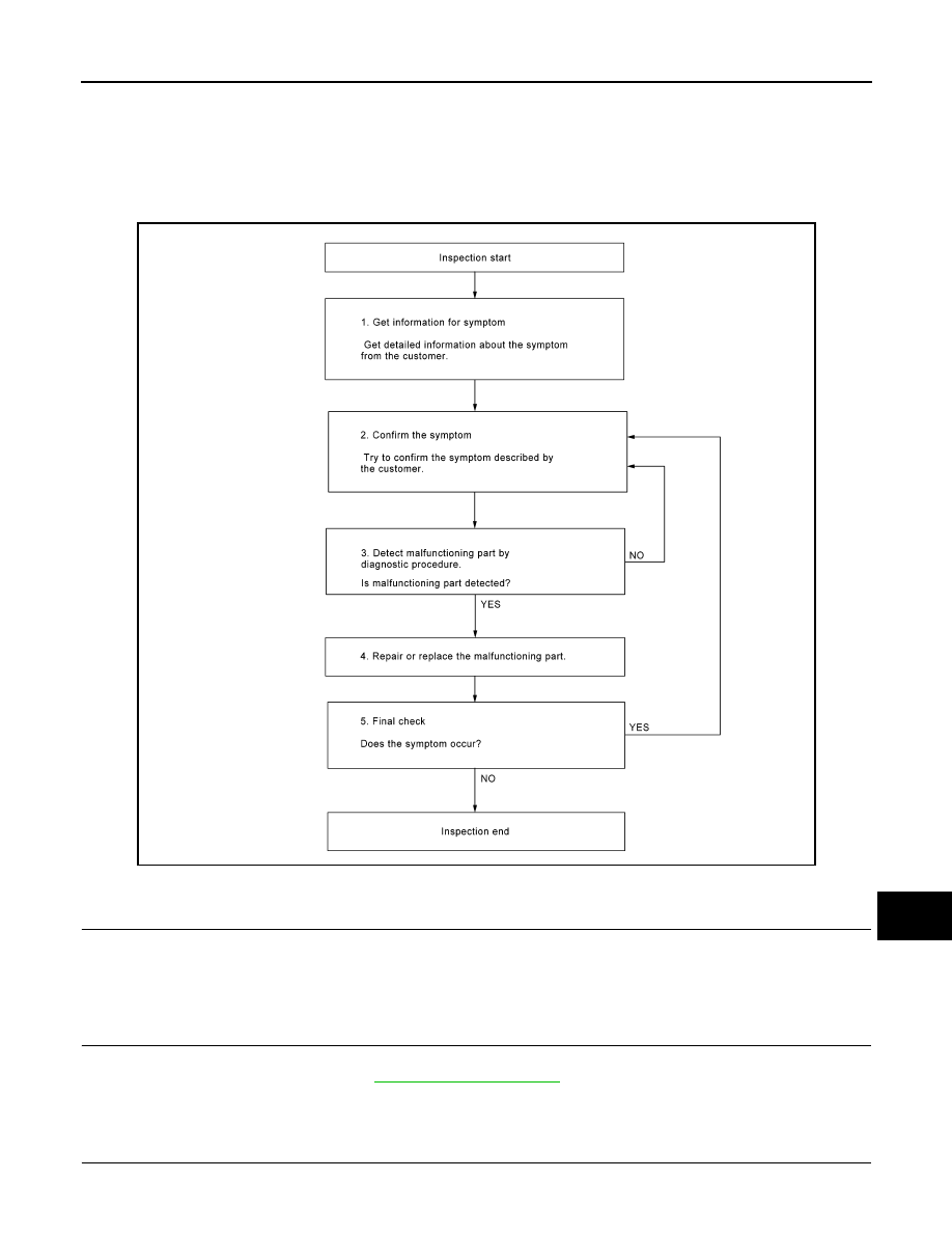
OVERALL SEQUENCE

DETAILED FLOW

1.

GET INFORMATION FOR SYMPTOM

Get detailed information from the customer about the symptom (the condition and the environment when the
incident/malfunction occurred).

>> GO TO 2.

2.

CONFIRM THE SYMPTOM

Try to confirm the symptom described by the customer. Verify relation between the symptom and the condition
when the symptom is detected. Refer to 

AV-109, "Symptom Table"

.

>> GO TO 3.

3.

DETECT MALFUNCTIONING PART BY DIAGNOSTIC PROCEDURE

Inspect according to Diagnostic Procedure of the system.

AWNIA2404GB

AV-94

< BASIC INSPECTION >

[DISPLAY AUDIO]

DIAGNOSIS AND REPAIR WORKFLOW

Is malfunctioning part detected?

YES

>> GO TO 4.

NO

>> GO TO 2.

4.

REPAIR OR REPLACE THE MALFUNCTIONING PART

1.

Repair or replace the malfunctioning part.

2.

Reconnect parts or connectors disconnected during Diagnostic Procedure.

>> GO TO 5.

5.

FINAL CHECK

Refer to confirmed symptom in step 2, and make sure that the symptom is not detected.

Was the repair confirmed?

YES

>> Inspection End.

NO

>> GO TO 2.

AV

INSPECTION AND ADJUSTMENT

AV-95

< BASIC INSPECTION >

[DISPLAY AUDIO]

C

D

E

F

G

H

I

J

K

L

M

B

A

O

P

INSPECTION AND ADJUSTMENT

PREDICTED COURSE LINE CENTER POSITION ADJUSTMENT

PREDICTED COURSE LINE CENTER POSITION ADJUSTMENT : Description

INFOID:0000000010500878

Adjust the center position of the predictive course line of the rear view monitor if it is shifted.

PREDICTED COURSE LINE CENTER POSITION ADJUSTMENT : Work Procedure

INFOID:0000000010500879

1.

DRIVING

Drive the vehicle straight ahead 100 m (328.1 ft) or more at a speed of 30 km/h (18.6 MPH) or more.

>> END

AV-96

< DTC/CIRCUIT DIAGNOSIS >

[DISPLAY AUDIO]

POWER SUPPLY AND GROUND CIRCUIT

DTC/CIRCUIT DIAGNOSIS

POWER SUPPLY AND GROUND CIRCUIT

AUDIO UNIT

AUDIO UNIT : Diagnosis Procedure

INFOID:0000000010435608

Regarding Wiring Diagram information, refer to 

AV-81, "Wiring Diagram"

.

1.

CHECK FUSE

Check that the following fuses are not blown.

Are the fuses blown?

YES

>> Replace the blown fuse after repairing the affected circuit.

NO

>> GO TO 2.

2.

CHECK POWER SUPPLY CIRCUIT

1.

Turn ignition switch OFF.

2.

Disconnect audio unit connector M10.

3.

Check voltage between audio unit connector M10 and ground.

Is the inspection result normal?

YES

>> GO TO 3.

NO

>> Repair or replace harness or connectors.

3.

CHECK GROUND CIRCUIT

1.

Turn ignition switch OFF.

2.

Disconnect audio unit connector M10.

3.

Check continuity between audio unit connectors and ground.

Is the inspection result normal?

YES

>> Inspection End.

NO

>> Repair or replace harness or connectors.

Terminal No.

Signal name

Fuse No.

7

Ignition power supply

4 (10A)

19

Battery power supply

19 (20A)

Audio unit

Ground

Condition

Voltage

(Approx.)

Connector

Terminal

M10

7

Ignition switch: ON

Battery voltage

19

Ignition switch: OFF

Audio unit

Ground

Continuity 

Connector

Terminal

M10

20

Yes


Content   ..  2099  2100  2101  2102   ..