Nissan Qashqai J11. Manual - part 2075


  Index      Nissan     Nissan Qashqai J11 - Service and Repair Manual


Search            


Content   ..  2073  2074  2075  2076   ..


Nissan Qashqai J11. Manual - part 2075


SN-94

< DTC/CIRCUIT DIAGNOSIS >

[WITH PARKING SPACE MEASUREMENT]

B272C CORNER SENSOR [FR]

B272C CORNER SENSOR [FR]

DTC Logic

INFOID:0000000010478054

DTC DETECTION LOGIC

Diagnosis Procedure

INFOID:0000000010478055

Regarding Wiring Diagram information, refer to 

SN-66, "Wiring Diagram"

.

1.

CHECK FRONT SONAR CORNER SENSOR RH CIRCUIT CONTINUITY

1.

Turn ignition switch OFF.

2.

Disconnect sonar control unit connector and front sonar corner sensor RH connector.

3.

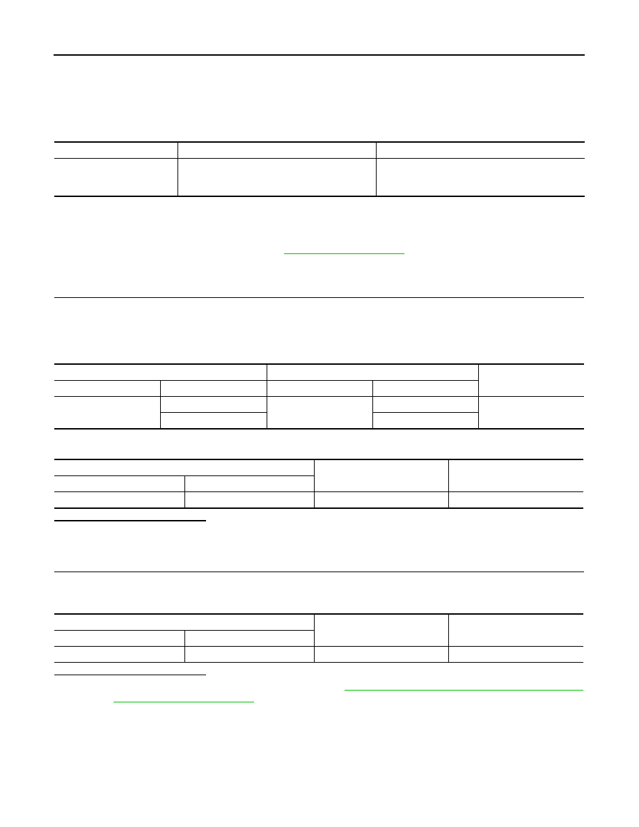
Check continuity between sonar control unit connector M61 and front sonar corner sensor RH connector
E124.

4.

Check continuity between sonar control unit connector M61 and ground.

Is the inspection result normal?

YES

>> GO TO 2.

NO

>> Repair or replace harness or connectors.

2.

CHECK FRONT SONAR CORNER SENSOR RH SIGNAL CIRCUIT SHORT TO BATTERY

1.

Turn ignition switch ON.

2.

Check voltage between sonar control unit connector M61 and ground.

Is the inspection result normal?

YES

>> Replace front sonar corner sensor RH. Refer to 

SN-100, "FRONT SENSOR : Removal and Instal-

lation - Front Sonar Sensors"

.

NO

>> Repair or replace harness or connectors.

CONSULT Display

DTC Detection Condition

Possible Cause

FRONT RIGHT SIDE EX-
TERNAL SENSOR
[B272C]

• Sensor is not configured.
• Sensor is open or short circuited.
• Sensor element malfunction.

• Sensor configuration.
• Harness or connectors.
• Front sonar sensor RH outer.

Sonar control unit

Front sonar sensor RH

Continuity

Connector

Terminal

Connector

Terminal

M61

30

E124

2

Yes

36

1

Sonar control unit

Ground

Continuity

Connector

Terminal

M61

30

No

Sonar control unit

Ground

Voltage

(Approx.)

Connector

Terminal

M61

30

0V

SN

B272D FRONT BUZZER

SN-95

< DTC/CIRCUIT DIAGNOSIS >

[WITH PARKING SPACE MEASUREMENT]

C

D

E

F

G

H

I

J

K

L

M

B

A

O

P

B272D FRONT BUZZER

DTC Logic

INFOID:0000000010478056

DTC DETECTION LOGIC

Diagnosis Procedure

INFOID:0000000010478057

Regarding Wiring Diagram information, refer to .

SN-66, "Wiring Diagram"

1.

CHECK FRONT SONAR BUZZER SIGNAL CIRCUIT CONTINUITY

1.

Turn ignition switch OFF.

2.

Disconnect sonar control unit connector and front sonar buzzer connector.

3.

Check continuity between sonar control unit connector M60 and front sonar buzzer connector M72.

4.

Check continuity between sonar control unit connector M60 and ground.

Is the inspection result normal?

YES

>> GO TO 2.

NO

>> Repair or replace harness or connectors.

2.

CHECK FRONT SONAR BUZZER SIGNAL CIRCUIT SHORT TO BATTERY

1.

Turn ignition switch ON.

2.

Check voltage between sonar control unit connector M60 and ground.

Is the inspection result normal?

YES

>> GO TO 3.

NO

>> Repair or replace harness or connectors.

3.

CHECK FRONT SONAR BUZZER SIGNAL CIRCUIT SHORT TO BUZZER POWER

1.

Turn ignition switch OFF.

2.

Check continuity between sonar control unit connector M60 terminals.

Is the inspection result normal?

CONSULT Display

DTC Detection Condition

Possible Cause

FRONT BUZZER
[B272D]

• Front buzzer is open or short circuited.
• Front buzzer malfunction.

• Harness or connectors.
• Front buzzer.

Sonar control unit

Front sonar buzzer

Continuity

Connector

Terminal

Connector

Terminal

M60

10

M72

3

Yes

Sonar control unit

Ground

Continuity

Connector

Terminal

M60

10

No

Sonar control unit

Ground

Voltage

(Approx.)

Connector

Terminal

M60

10

0V

Sonar control unit connector M60

Continuity

Terminal

Terminal

2

10

No

SN-96

< DTC/CIRCUIT DIAGNOSIS >

[WITH PARKING SPACE MEASUREMENT]

B272D FRONT BUZZER

YES

>> Replace front sonar buzzer. Refer to 

SN-105, "BUZZER : Removal and Installation - Front"

.

NO

>> Repair or replace harness or connectors.

SN

PARKING SPACE MEASUREMENT SWITCH

SN-97

< DTC/CIRCUIT DIAGNOSIS >

[WITH PARKING SPACE MEASUREMENT]

C

D

E

F

G

H

I

J

K

L

M

B

A

O

P

PARKING SPACE MEASUREMENT SWITCH

Diagnosis Procedure

INFOID:0000000010478167

Regarding Wiring Diagram information, refer to 

SN-66, "Wiring Diagram"

.

1.

CHECK PARKING SPACE MEASUREMENT SWITCH SIGNAL CIRCUIT CONTINUITY

1.

Turn ignition switch OFF.

2.

Disconnect sonar control unit connector and parking space measurement switch connector.

3.

Check continuity between sonar control unit connector M60 and parking space measurement switch con-
nector.

*1:Exept for HR engine models with CVT or MR16DDT engine models or Korean models

:2:Only for HR engine models with CVT, MR16DDT engine models and Korean models

4.

Check continuity between sonar control unit connector M60 and ground.

Is the inspection result normal?

YES

>> GO TO 2.

NO

>> Repair or replace harness or connectors.

2.

CHECK PARKING SPACE MEASUREMENT SWITCH SIGNAL CIRCUIT SHORT TO BATTERY

1.

Turn ignition switch ON.

2.

Check voltage between parking space measurement switch connector and ground.

*1:Exept for HR engine models with CVT or MR16DDT engine models or Korean models

:2:Only for HR engine models with CVT, MR16DDT engine models and Korean models

Is the inspection result normal?

YES

>> Replace parking space measurement switch.

NO

>> Repair or replace harness or connectors.

Sonar control unit

Parking space measurement

Continuity

Connector

Terminal

Connector

Terminal

M60

16

M112

*1

M104

*2

1

Yes

Sonar control unit

Ground

Continuity

Connector

Terminal

M60

16

No

Parking space measurement

Ground

Continuity

Connector

Terminal

M112

*1

M104

*2

2

Yes


Content   ..  2073  2074  2075  2076   ..