Content .. 2058 2059 2060 2061 ..
Nissan Qashqai J11. Manual - part 2060
SN-34
< DTC/CIRCUIT DIAGNOSIS >
[WITHOUT PARKING SPACE MEASUREMENT]
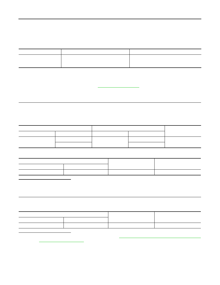
B2722 CENTER SENSOR [RR]
B2722 CENTER SENSOR [RR]
DTC Logic
INFOID:0000000010477984
DTC DETECTION LOGIC
Diagnosis Procedure
INFOID:0000000010477985
Regarding Wiring Diagram information, refer to
1.
CHECK REAR SONAR CENTER SENSOR RH SIGNAL CIRCUIT CONTINUITY
1.
Turn ignition switch OFF.
2.
Disconnect sonar control unit connector and rear sonar center sensor RH connector.
3.
Check continuity between sonar control unit connector M59 and rear sonar center sensor RH connector
B115.
4.
Check continuity between sonar control unit connector M59 and ground.
Is the inspection result normal?
YES
>> GO TO 2.
NO
>> Repair or replace harness or connectors.
2.
CHECK REAR SONAR CENTER SENSOR RH SIGNAL CIRCUIT SHORT TO BATTERY
1.
Turn ignition switch ON.
2.
Check voltage between sonar control unit connector M59 and ground.
Is the inspection result normal?
YES
>> Replace rear sonar center sensor RH. Refer to
SN-49, "REAR SENSOR : Removal and Installa-
.
NO
>> Repair or replace harness or connectors.
CONSULT Display
DTC Detection Condition
Possible Cause
REAR RIGHT SIDE INTER-
NAL SENSOR
[B2722]
• Sensor is not configured.
• Sensor is open or short circuited.
• Sensor element malfunction.
• Sensor configuration.
• Harness or connectors.
• Rear sonar sensor RH inner.
Sonar control unit
Rear sonar sensor RH
Continuity
Connector
Terminal
Connector
Terminal
M59
9
B115
2
Yes
14
1
Sonar control unit
Ground
Continuity
Connector
Terminal
M59
9
—
No
Sonar control unit
Ground
Voltage
(Approx.)
Connector
Terminal
M59
9
—
0V