Nissan Qashqai J11. Manual - part 2051


  Index      Nissan     Nissan Qashqai J11 - Service and Repair Manual


Search            


Content   ..  2049  2050  2051  2052   ..


Nissan Qashqai J11. Manual - part 2051


WCS-52

< SYMPTOM DIAGNOSIS >

THE SEAT BELT REMINDER WARNING CONTINUES SOUNDING, OR DOES 

NOT SOUND

THE SEAT BELT REMINDER WARNING CONTINUES SOUNDING, OR
DOES NOT SOUND

Description

INFOID:0000000010438797

• Seat belt warning does not sound even though driver seat belt is not fastened.
• Seat belt warning sounds even though driver seat belt is fastened.

Diagnosis Procedure

INFOID:0000000010438798

1.

CHECK WARNING CHIME OPERATION

1.

Select "BUZZER" of "BCM" on "CONSULT".

2.

Perform "SEAT BELT WARN TEST" of "ACTIVE TEST".

Is the inspection result normal?

YES

>> GO TO 2.

NO

>> Replace combination meter. Refer to 

MWI-80, "Removal and Installation"

.

2.

CHECK COMBINATION METER INPUT SIGNAL

Check the combination meter input signal. Refer to 

WCS-44, "Component Function Check"

Is the inspection result normal?

YES

>> Replace BCM. Refer to 

BCS-132, "Removal and Installation"

.

NO

>> GO TO 3.

3.

CHECK SEAT BELT BUCKLE SWITCH LH CIRCUIT

Check the seat belt buckle switch LH circuit. Refer to 

SBC-14, "Component Inspection"

Is the inspection result normal?

YES

>> GO TO 4.

NO

>> Repair or replace harness or connector.

4.

CHECK SEAT BELT BUCKLE SWITCH LH

Check the seat belt buckle switch LH. Refer to 

SBC-14, "Component Inspection"

.

Is the inspection result normal?

YES

>> Replace the combination meter. Refer to 

MWI-80, "Removal and Installation"

.

NO

>> Replace the seat belt buckle switch LH. Refer to 

SB-8, "FRONT SEAT BELT BUCKLE : Removal

and Installation"

.

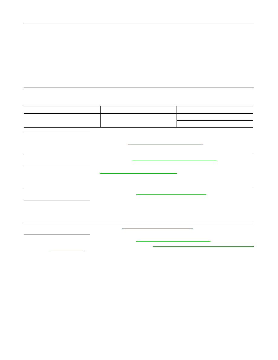
Component

CONSULT

Condition

Buzzer

SEAT BELT WARN TEST

ON

OFF

WCS

THE LIGHT REMINDER WARNING DOES NOT SOUND

WCS-53

< SYMPTOM DIAGNOSIS >

C

D

E

F

G

H

I

J

K

L

M

B

A

O

P

THE LIGHT REMINDER WARNING DOES NOT SOUND

Description

INFOID:0000000010438799

Light reminder warning does not sound even though headlamp is illuminated.

Diagnosis Procedure

INFOID:0000000010438800

1.

CHECK COMBINATION METER INPUT SIGNAL

Select the "Data Monitor" for the "METER/M&A" and check the "BUZZER" monitor value.

Is the inspection result normal?

YES

>> Replace combination meter. Refer to 

MWI-80, "Removal and Installation"

.

NO

>> GO TO 2.

2.

CHECK FRONT DOOR SWITCH LH SIGNAL CIRCUIT

Check the front door switch LH signal circuit. Refer to 

DLK-284, "Diagnosis Procedure"

.

Is the inspection result normal?

YES

>> GO TO 3.

NO

>> Repair or replace harness or connector.

3.

CHECK FRONT DOOR SWITCH LH

Check the front door switch LH. Refer to 

DLK-286, "Component Inspection"

.

Is the inspection result normal?

YES

>> Replace the BCM. Refer to 

BCS-132, "Removal and Installation"

.

NO

>> Replace the front door switch LH. Refer to 

DLK-376, "Removal and Installation"

.

Monitor item

Condition

Status

BUZZER

Under the condition of buzzer input

On

Except above

Off

WCS-54

< SYMPTOM DIAGNOSIS >

THE KEY WARNING DOES NOT SOUND (WITHOUT INTELLIGENT KEY)

THE KEY WARNING DOES NOT SOUND (WITHOUT INTELLIGENT KEY)

Description

INFOID:0000000010438801

The key warning chime does not sound, when all of the following conditions are fulfilled:
• Key inserted into the key cylinder (key switch signal ON).
• Ignition switch is in OFF position (ignition switch signal OFF).
• Driver side door is open (front door switch LH ON)

Diagnosis Procedure

INFOID:0000000010438802

1.

CHECK BCM INPUT SIGNAL

1.

Connect CONSULT.

2.

Select the "DATA MONITOR" of "BCM (BUZZER)" and check the "KEY ON SW" monitor value.

Is the inspection result normal?

YES

>> Replace the BCM. Refer to 

BCS-132, "Removal and Installation"

.

NO

>> GO TO 2.

2.

CHECK KEY SWITCH SIGNAL CIRCUIT

Check the key switch signal circuit. Refer to 

WCS-48, "Diagnosis Procedure"

Is the inspection result normal?

YES

>> GO TO 3.

NO

>> Repair or replace harness or connector.

3.

CHECK KEY SWITCH 

Check the key switch. Refer to 

WCS-49, "Component Inspection"

Is the inspection result normal?

YES

>> Replace the BCM. Refer to 

BCS-132, "Removal and Installation"

.

NO

>> Replace key switch.

Monitor item

Condition

Status

KEY ON SW

Under the condition of buzzer input

On

Except above

Off

SN

SN-1

DRIVER INFORMATION & MULTIMEDIA

C

D

E

F

G

H

I

J

K

L

M

B

SECTION 

SN

A

O

P

CONTENTS

SONAR SYSTEM

WITHOUT PARKING SPACE MEASURE-

MENT

PRECAUTION ...............................................

4

PRECAUTION .....................................................

4

Precaution for Supplemental Restraint System 
(SRS) "AIR BAG" and "SEAT BELT PRE-TEN-
SIONER" .................................................................
..

4

Precautions for Removing Battery Terminal  .............

4

Precautions Necessary for Steering Wheel Rota-
tion after Battery Disconnect  ...................................
..

5

SYSTEM DESCRIPTION  ..............................

7

COMPONENT PARTS  ........................................

7

Component Parts Location ........................................

7

Component Description .............................................

8

SYSTEM ..............................................................

9

System Diagram ........................................................

9

System Description  ...................................................

9

DIAGNOSIS SYSTEM (SONAR CONTROL 
UNIT) ..................................................................

11

CONSULT Function  ................................................

11

ECU DIAGNOSIS INFORMATION  ..............

13

SONAR CONTROL UNIT ...................................

13

Reference Value  .....................................................

13

DTC Index  ...............................................................

15

WIRING DIAGRAM  ......................................

17

SONAR SYSTEM  ...............................................

17

Wiring Diagram  .......................................................

17

BASIC INSPECTION  ...................................

26

DIAGNOSIS AND REPAIR WORKFLOW  .........

26

Work Flow  ...............................................................

26

INSPECTION AND ADJUSTMENT  ..................

28

ADDITIONAL SERVICE WHEN REPLACING SO-
NAR CONTROL UNIT ................................................

28

ADDITIONAL SERVICE WHEN REPLACING SO-
NAR CONTROL UNIT : Description  ........................

28

ADDITIONAL SERVICE WHEN REPLACING SO-
NAR CONTROL UNIT : Work Procedure  ................

28

CONFIGURATION (SONAR CONTROL UNIT) .........

28

CONFIGURATION (SONAR CONTROL UNIT) : 
Description ...............................................................

29

CONFIGURATION (SONAR CONTROL UNIT) : 
Work Procedure .......................................................

29

CONFIGURATION (SONAR CONTROL UNIT) : 
Configuration List .....................................................

30

DTC/CIRCUIT DIAGNOSIS  .........................

31

U1000 CAN COMM CIRCUIT  ...........................

31

DTC Logic ................................................................

31

Diagnosis Procedure  ...............................................

31

U1010 CONTROL UNIT (CAN) .........................

32

DTC Logic ................................................................

32

B2720 CORNER SENSOR [RL]  .......................

33

DTC Logic ................................................................

33

Diagnosis Procedure  ...............................................

33

B2721 CENTER SENSOR [RL]  ........................

34

DTC Logic ................................................................

34

Diagnosis Procedure  ...............................................

34

B2722 CENTER SENSOR [RR] ........................

35

DTC Logic ................................................................

35

Diagnosis Procedure  ...............................................

35

B2723 CORNER SENSOR [RR] .......................

36

DTC Logic ................................................................

36

Diagnosis Procedure  ...............................................

36

B2724 SONAR CONTROL UNIT  ......................

37


Content   ..  2049  2050  2051  2052   ..