Content .. 1948 1949 1950 1951 ..
Nissan Qashqai J11. Manual - part 1950
PCS-72
< SYSTEM DESCRIPTION >
[POWER DISTRIBUTION SYSTEM]
COMPONENT PARTS
SYSTEM DESCRIPTION
COMPONENT PARTS
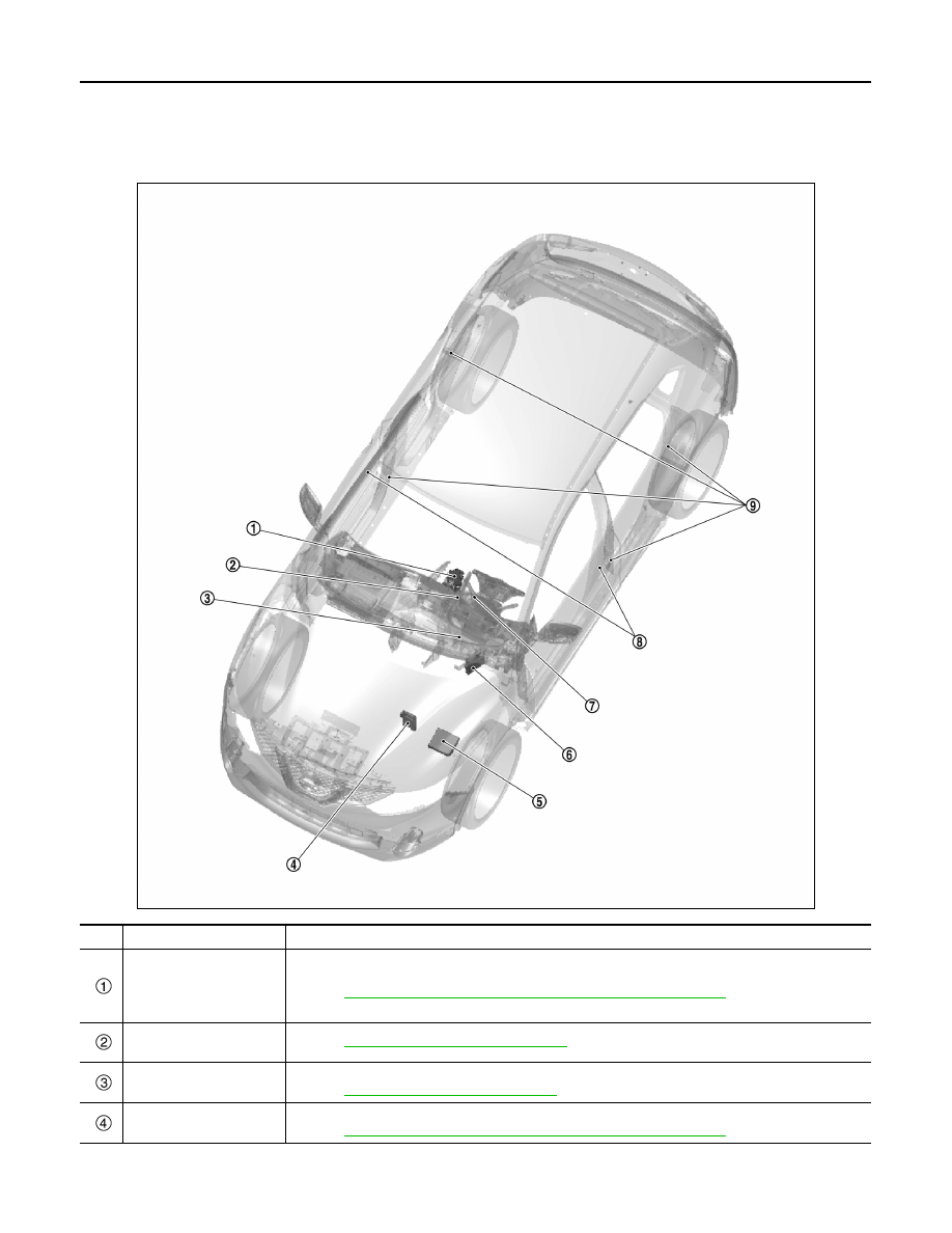
Component Parts Location
INFOID:0000000010434039
JMMIA1776ZZ
No.
Component
Description
CVT shift selector (deten-
tion switch) (CVT models)
CVT shift selector (detention switch) detects shift lever status, transmits detention switch signal to
BCM.
Refer to
TM-430, "CVT CONTROL SYSTEM : Component Parts Location"
for detailed installation
location.
Push-button ignition
switch
Refer to
PCS-73, "Push-button Ignition Switch"
Stop lamp switch
Stop lamp switch detects that brake pedal is depressed, and transmits the signal to BCM.
Refer to
BRC-8, "Component Parts Location"
TCM
Transmits shif position signal to BCM via CAN communication line.
Refer to