Nissan Qashqai J11. Manual - part 1876


  Index      Nissan     Nissan Qashqai J11 - Service and Repair Manual


Search            


Content   ..  1874  1875  1876  1877   ..


Nissan Qashqai J11. Manual - part 1876


LAN

BCM BRANCH LINE CIRCUIT

LAN-97

< DTC/CIRCUIT DIAGNOSIS >

[CAN]

C

D

E

F

G

H

I

J

K

L

B

A

O

P

N

BCM BRANCH LINE CIRCUIT

Diagnosis Procedure

INFOID:0000000010376797

1.

CHECK DTC

Check DTC of the CAN gateway with CONSULT.
Is B2600-46 or B2600-55 indicated?

YES

>> Perform a diagnosis of the indicated DTC.

NO

>> GO TO 2.

2.

CHECK CONNECTOR

1.

Turn the ignition switch OFF.

2.

Disconnect the battery cable from the negative terminal.

3.

Check the terminals and connectors of BCM for damage, bend and loose connection (unit side and con-
nector side).

Is the inspection result normal?

YES

>> GO TO 3.

NO

>> Repair the terminal and connector.

3.

CHECK HARNESS FOR OPEN CIRCUIT

1.

Disconnect the connector of BCM.

2.

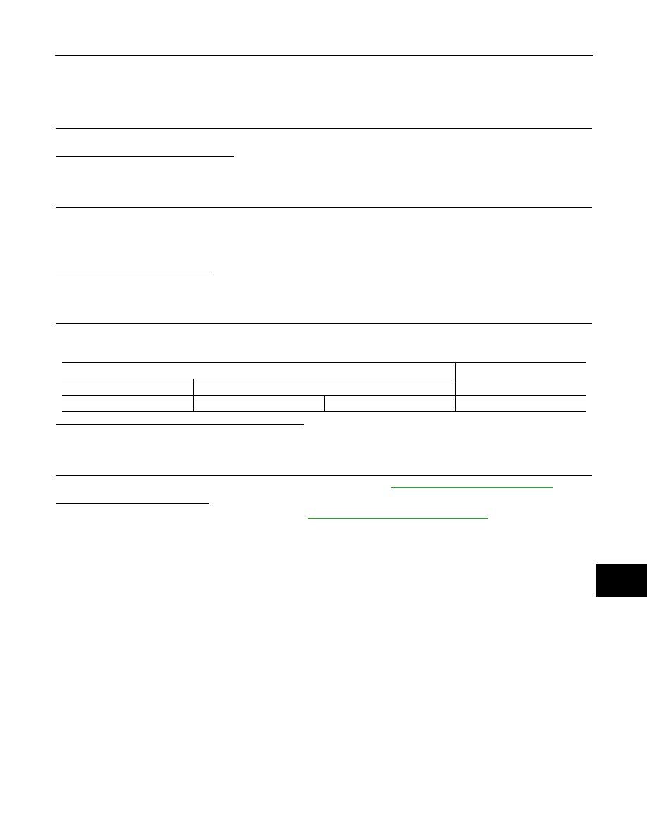
Check the resistance between the BCM harness connector terminals.

Is the measurement value within the specification?

YES

>> GO TO 4.

NO

>> Repair the BCM branch line.

4.

CHECK POWER SUPPLY AND GROUND CIRCUIT

Check the power supply and the ground circuit of the BCM. Refer to 

BCS-128, "Diagnosis Procedure"

.

Is the inspection result normal?

YES (Present error)>>Replace the BCM. Refer to 

BCS-135, "Removal and Installation"

.

YES (Past error)>>Error was detected in the BCM branch line.
NO

>> Repair the power supply and the ground circuit.

BCM harness connector

Resistance (

)

Connector No.

Terminal No.

B4

20

40

Approx. 54 – 66

LAN-98

< DTC/CIRCUIT DIAGNOSIS >

[CAN]

AV BRANCH LINE CIRCUIT

AV BRANCH LINE CIRCUIT

Diagnosis Procedure

INFOID:0000000010272952

1.

CHECK CONNECTOR

1.

Turn the ignition switch OFF.

2.

Disconnect the battery cable from the negative terminal.

3.

Check the following terminals and connectors for damage, bend and loose connection (unit side and con-
nector side).

-

NAVI control unit

-

BCM

Is the inspection result normal?

YES

>> GO TO 2.

NO

>> Repair the terminal and connector.

2.

CHECK HARNESS CONTINUITY (OPEN CIRCUIT)

1.

Disconnect the connector of BCM.

2.

Check the continuity between the BCM harness connector terminals.

Is the inspection result normal?

YES

>> GO TO 3.

NO

>> Check the harness and repair the root cause (CAN communication circuit 2 side).

3.

CHECK HARNESS FOR OPEN CIRCUIT

1.

Connect the connector of BCM.

2.

Disconnect the connector of NAVI control unit.

3.

Check the resistance between the NAVI control unit harness connector terminals.

Is the measurement value within the specification?

YES

>> GO TO 4.

NO

>> Repair the NAVI control unit branch line.

4.

CHECK POWER SUPPLY AND GROUND CIRCUIT

Check the power supply and the ground circuit of the NAVI control unit. Refer to 

AV-239, "AV CONTROL UNIT

: Diagnosis Procedure"

.

Is the inspection result normal?

YES (Present error)>>Replace the NAVI control unit. Refer to 

AV-268, "Removal and Installation"

.

YES (Past error)>>Error was detected in the NAVI control unit branch line.
NO

>> Repair the power supply and the ground circuit.

BCM harness connector

Continuity

Connector No.

Terminal No.

M70

46

48

Existed

45

49

Existed

NAVI control unit harness connector

Resistance (

)

Connector No.

Terminal No.

M48

8

17

Approx. 54 – 66

LAN

AVM BRANCH LINE CIRCUIT

LAN-99

< DTC/CIRCUIT DIAGNOSIS >

[CAN]

C

D

E

F

G

H

I

J

K

L

B

A

O

P

N

AVM BRANCH LINE CIRCUIT

Diagnosis Procedure

INFOID:0000000010272953

1.

CHECK CONNECTOR

1.

Turn the ignition switch OFF.

2.

Disconnect the battery cable from the negative terminal.

3.

Check the following terminals and connectors for damage, bend and loose connection (unit side and con-
nector side).

-

Around view monitor control unit

-

BCM

Is the inspection result normal?

YES

>> GO TO 2.

NO

>> Repair the terminal and connector.

2.

CHECK HARNESS CONTINUITY (OPEN CIRCUIT)

1.

Disconnect the connector of BCM.

2.

Check the continuity between the BCM harness connector terminals.

Is the inspection result normal?

YES

>> GO TO 3.

NO

>> Check the harness and repair the root cause (CAN communication circuit 2 side).

3.

CHECK HARNESS FOR OPEN CIRCUIT

1.

Connect the connector of BCM.

2.

Disconnect the connector of around view monitor control unit.

3.

Check the resistance between the around view monitor control unit harness connector terminals.

-

With pump control unit

-

Without pump control unit

Is the measurement value within the specification?

YES

>> GO TO 4.

NO

>> Repair the around view monitor control unit branch line.

4.

CHECK POWER SUPPLY AND GROUND CIRCUIT

Check the power supply and the ground circuit of the around view monitor control unit. Refer to 

AV-239,

"AROUND VIEW MONITOR CONTROL UNIT : Diagnosis Procedure"

.

Is the inspection result normal?

YES (Present error)>>Replace the around view monitor control unit. Refer to 

AV-276, "Removal and Installa-

tion"

.

YES (Past error)>>Error was detected in the around view monitor control unit branch line.
NO

>> Repair the power supply and the ground circuit.

BCM harness connector

Continuity

Connector No.

Terminal No.

M70

46

48

Existed

45

49

Existed

Around view monitor control unit harness connector

Resistance (

)

Connector No.

Terminal No.

M7

27

28

Approx. 54 – 66

Around view monitor control unit harness connector

Resistance (

)

Connector No.

Terminal No.

M95

12

10

Approx. 54 – 66

LAN-100

< DTC/CIRCUIT DIAGNOSIS >

[CAN]

HVAC BRANCH LINE CIRCUIT

HVAC BRANCH LINE CIRCUIT

Diagnosis Procedure

INFOID:0000000010272954

1.

CHECK CONNECTOR

1.

Turn the ignition switch OFF.

2.

Disconnect the battery cable from the negative terminal.

3.

Check the following terminals and connectors for damage, bend and loose connection (unit side and con-
nector side).

-

A/C amp. (Except automatic air conditioner)

-

A/C auto amp. (With automatic air conditioner)

-

Harness connector M137 (With automatic air conditioner)

-

Harness connector M42 (With automatic air conditioner)

-

BCM

Is the inspection result normal?

YES

>> GO TO 2.

NO

>> Repair the terminal and connector.

2.

CHECK HARNESS CONTINUITY (OPEN CIRCUIT)

1.

Disconnect the connector of BCM.

2.

Check the continuity between the BCM harness connector terminals.

Is the inspection result normal?

YES-1 >> Except automatic air conditioner: GO TO 3.
YES-2 >> With automatic air conditioner: GO TO 5.
NO

>> Check the harness and repair the root cause (CAN communication circuit 2 side).

3.

CHECK HARNESS FOR OPEN CIRCUIT

1.

Connect the connector of BCM.

2.

Disconnect the connector of A/C amp.

3.

Check the resistance between the A/C amp. harness connector terminals.

Is the measurement value within the specification?

YES

>> GO TO 4.

NO

>> Repair the A/C amp. branch line.

4.

CHECK POWER SUPPLY AND GROUND CIRCUIT

Check the power supply and the ground circuit of the A/C amp. Refer to the following.
• Manual air conditioning: 

HAC-207, "A/C AMP. : Diagnosis Procedure"

• Manual heater: 

HAC-284, "A/C AMP. : Diagnosis Procedure"

Is the inspection result normal?

YES (Present error)>>Replace the A/C amp. Refer to the following.

• Manual air conditioning: 

HAC-226, "Removal and Installation"

• Manual heater: 

HAC-295, "Removal and Installation"

YES (Past error)>>Error was detected in the A/C amp. branch line.
NO

>> Repair the power supply and the ground circuit.

5.

CHECK HARNESS FOR OPEN CIRCUIT

1.

Connect the connector of BCM.

BCM harness connector

Continuity

Connector No.

Terminal No.

M70

46

48

Existed

45

49

Existed

A/C amp. harness connector

Resistance (

)

Connector No.

Terminal No.

M50

7

23

Approx. 54 – 66


Content   ..  1874  1875  1876  1877   ..