Content .. 1859 1860 1861 1862 ..
Nissan Qashqai J11. Manual - part 1861
LAN
COMPONENT PARTS
LAN-37
< SYSTEM DESCRIPTION >
[CAN]
C
D
E
F
G
H
I
J
K
L
B
A
O
P
N
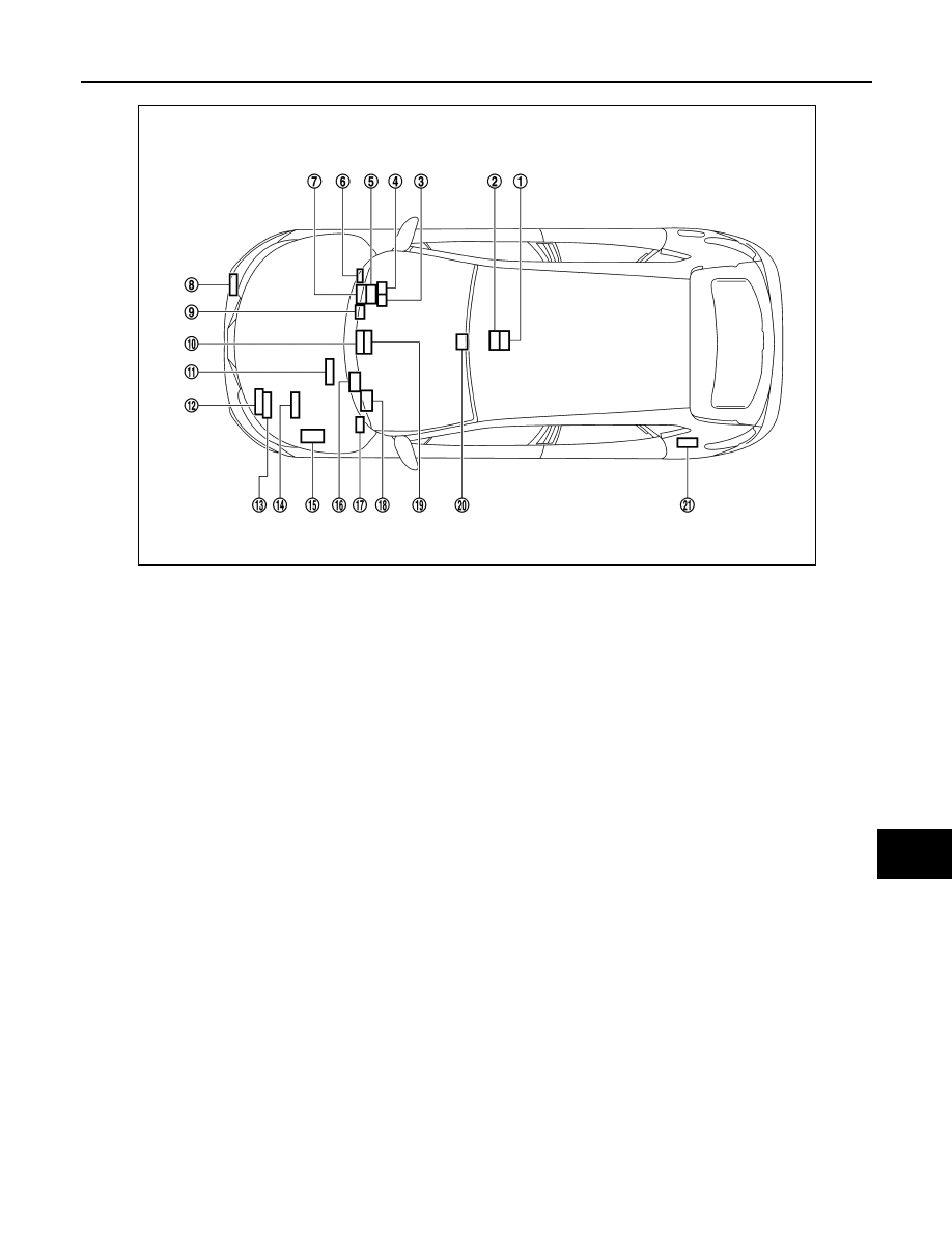
1.
Electric park brake control unit
2.
Air bag diagnosis sensor unit
3.
Not applicable
4.
Steering angle sensor
5.
Combination meter
6.
Data link connector
7.
EPS control unit
8.
Distance sensor
9.
Sonar control unit
10. NAVI control unit
11.
ABS actuator and electric unit (con-
trol unit)
12. TCM (HRA2DDT and R9M engine
models)
13. ECM
14. TCM (MR20DD engine models)
15. IPDM E/R
16. Around view monitor control unit
17. BCM
18. Chassis control module
19. • A/C auto amp. (With auto A/C)
• A/C amp. (Without auto A/C)
20. Front camera unit
21. 4WD control unit
JSMIA1783ZZ