Content .. 1835 1836 1837 1838 ..
Nissan Qashqai J11. Manual - part 1837
BCS-74
< ECU DIAGNOSIS INFORMATION >
BCM
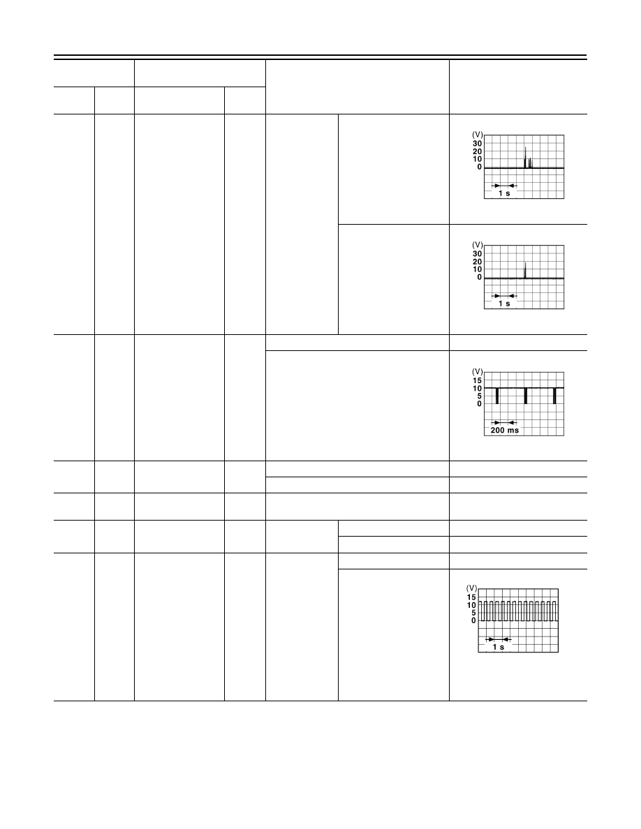
24*
3
(G)
Ground
Rear bumper anten-
na (+)
Output
Power position
ON and any
door is open
Intelligent Key is outside
the vehicle
Intelligent Key is inside
the vehicle
38
(G)
Ground
Alarm link
Output
Disarmed phase
0 V
Armed phase
39
(W)
Ground
High-mounted stop
lamp output
Output
Brake pedal is not depressed
0 V
Brake pedal is depressed
9 - 16 V
40
(P)
Ground
CAN-L (CAN com-
munication circuit 1)
Input/
Output
—
—
41*
3
(V)
Ground
Steering lock unit
power supply output
Output
Steering lock
unit
Activated
9 – 16 V
Not activated
0 – 0.5 V
42
(G)
Ground
Turn signal LH out-
put (Side)
Output
Ignition switch
ON
Turn signal switch OFF
0 V
Turn signal switch LH
6.5 V
(Turn signal lamp turn on: 9 - 16
V)
Terminal No.
(Wire color)
Description
Condition
Value
(Approx.)
+
−
Signal name
Input/
Output
JSMIA1507GB
JSMIA1506GB
JSMIA1405GB
PKID0926E