Content .. 1772 1773 1774 1775 ..
Nissan Qashqai J11. Manual - part 1774
LUGGAGE ROOM LAMP CIRCUIT
INL-61
< DTC/CIRCUIT DIAGNOSIS >
C
D
E
F
G
H
I
J
K
M
A
B
INL
N
O
P
Is the inspection result normal?
YES
>> Replace luggage room lamp.
NO
>> Repair or replace harnesses.
4.
CHECK LUGGAGE ROOM LAMP SHORT CIRCUIT
1.
Disconnect BCM connector.
2.
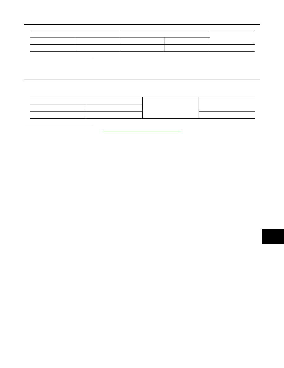
Check continuity between BCM harness connector and ground.
Is the inspection result normal?
YES
>> Replace BCM. Refer to
BCS-132, "Removal and Installation"
.
NO
>> Repair or replace harnesses.
BCM
Luggage room lamp
Continuity
Connector
Terminal
Connector
Terminal
B3
127
B49
4
Existed
BCM
Ground
Continuity
Connector
Terminal
B3
127
Not existed