Content .. 1740 1741 1742 1743 ..
Nissan Qashqai J11. Manual - part 1742
EXL-270
< DTC/CIRCUIT DIAGNOSIS >
[HALOGEN HEADLAMP]
B20D5 TAIL LAMP RH POWER SUPPLY CIRCUIT
B20D5 TAIL LAMP RH POWER SUPPLY CIRCUIT
DTC Description
INFOID:0000000010469960
DTC DETECTION LOGIC
POSSIBLE CAUSE
• Harness or connector
• Rear combination lamp RH (body side) internal circuit
- LED (Tail lamp)
- Harness
• Rear combination lamp RH (back door side) internal circuit
- LED (tail lamp)
- Harness
• IPDM E/R
FAIL-SAFE
Shuts off the power supply to the following power supply circuits until the parking lamp, license plate lamp, and
tail lamp ON conditions are no longer satisfied.
• Tail lamp RH (body side)
• Tail lamp RH (back door side)
DTC CONFIRMATION PROCEDURE
1.
PRECONDITIONING
With CONSULT
1.
Turn ignition switch ON.
2.
Select “T LAMP RH CIRC MALFUNCTN” in “Data Monitor” mode of “IPDM E/R” using CONSULT.
3.
Check the monitor status.
What is the monitor status?
“0”
>> GO TO 2.
“1”
>> A short circuit is detected multiple times in the tail lamp RH (body side) or tail lamp RH (back door
side) power supply circuit, and damage accumulates at the smart FET inside the IPDM E/R. For
this reason, IPDM E/R does not turn ON the smart FET. Because the DTC cannot be reproduced
in this state, perform
EXL-271, "Diagnosis Procedure"
and replace IPDM E/R after the malfunc-
tioning part is repaired. Refer to
PCS-67, "Removal and Installation"
2.
PERFORM DTC CONFIRMATION PROCEDURE
With CONSULT
1.
Turn ignition switch OFF.
2.
Turn ignition switch ON.
3.
Turn lighting switch 1ST.
4.
Select “Self Diagnostic Result” mode of “IPDM E/R” using CONSULT.
5.
Check DTC.
Is DTC detected?
YES
>> Refer to
EXL-271, "Diagnosis Procedure"
.
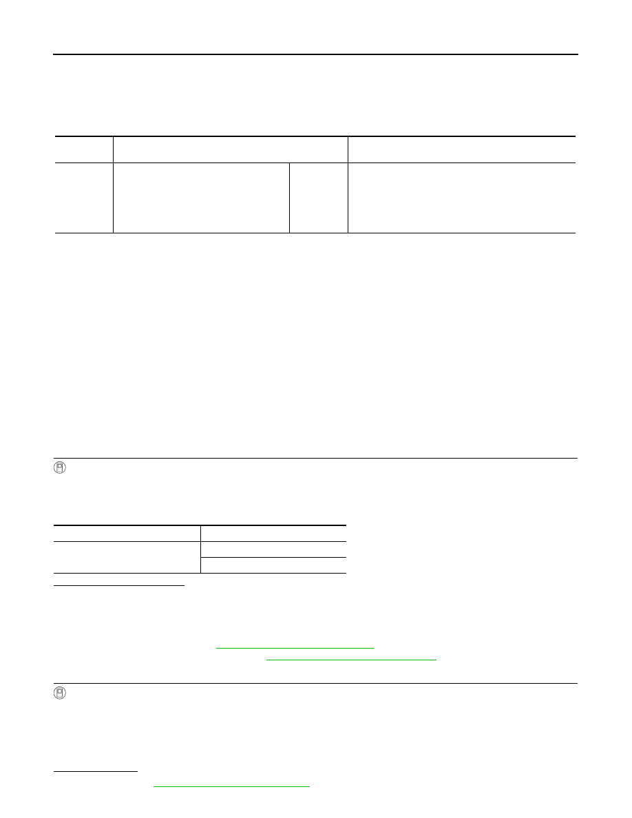
DTC No.
CONSULT screen terms
(Trouble diagnosis content)
DTC detection condition
B20D5
TAIL LAMP RH PWR SPLY CIRC
(Tail lamp right hand power supply circuit)
[CIRC
SHORT TO
GRND]
When the parking lamp, license plate lamp, and tail lamp
ON conditions are satisfied (smart FET inside IPDM E/R
is ON), and overcurrent is detected in the following power
supply circuit.
• Tail lamp RH (body side)
• Tail lamp RH (back door side)
Monitor item
Monitor status
T LAMP RH CIRC MALFUNCTN
0
1