Content .. 1735 1736 1737 1738 ..
Nissan Qashqai J11. Manual - part 1737
EXL-250
< DTC/CIRCUIT DIAGNOSIS >
[HALOGEN HEADLAMP]
B1256 FRONT FOG LAMP RH POWER SUPPLY CIRCUIT
4.
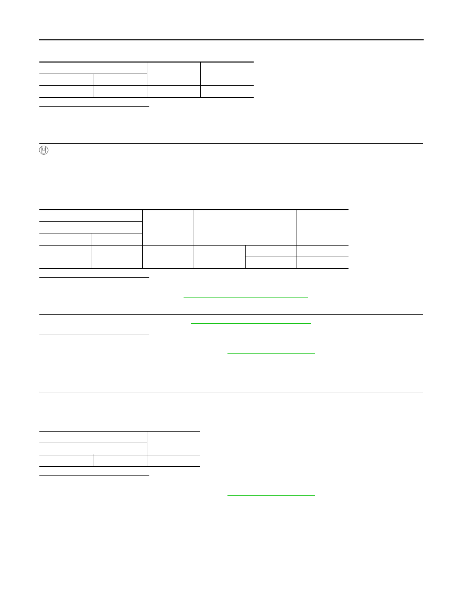
Check continuity between IPDM E/R harness connector and ground.
Is the inspection result normal?
YES
>> GO TO 2.
NO
>> Repair or replace harness.
2.
CHECK FRONT FOG LAMP RH POWER SUPPLY
With CONSULT
1.
Connect IPDM E/R connector.
2.
Turn ignition switch ON
3.
Select “FRONT FOG LAMP” in “Active Test” mode of “IPDM E/R” using CONSULT.
4.
With operating the test items, check the voltage between front fog lamp RH harness connector and
ground.
Is the inspection result normal?
YES
>> GO TO 3.
NO
>> Replace IPDM E/R. Refer to
PCS-67, "Removal and Installation"
3.
CHECK FRONT FOG LAMP RH BULB
Check the front fog lamp RH bulb. Refer to
EXL-250, "Component Inspection"
.
Is the inspection result normal?
YES
>> INSPECTION END
NO
>> Replace front fog lamp RH bulb. Refer to
Component Inspection
INFOID:0000000010469929
1.
CHECK FRONT FOG LAMP RH BULB
1.
Turn ignition switch OFF.
2.
Disconnect front fog lamp RH connector.
3.
Check resistance of front fog lamp RH terminals.
Is the inspection result normal?
YES
>> INSPECTION END
NO
>> Replace front fog lamp RH bulb. Refer to
IPDM E/R
—
Continuity
Connector
Terminal
E101
49
Ground
Not existed
+
-
Test item
Voltage
Front fog lamp RH
Connector
Terminal
E95
1
Ground
FRONT FOG
LAMP
On
9 – 16 V
Off
0 – 1 V
Front fog lamp RH
Resistance
Terminal
1
2
Except 0
Ω