Nissan Qashqai J11. Manual - part 1639


  Index      Nissan     Nissan Qashqai J11 - Service and Repair Manual


Search            


Content   ..  1637  1638  1639  1640   ..


Nissan Qashqai J11. Manual - part 1639


BRM-384

< PRECAUTION >

[EXCEPT FOR EUROPE AND RUSSIA (RHD)]

PRECAUTIONS

PRECAUTION

PRECAUTIONS

Precautions for Removing Battery Terminal

INFOID:0000000010503257

• With the adoption of Auto ACC function, ACC power is automatically supplied by operating the intelligent key

or remote keyless entry or by opening/closing the driver side door. In addition, ACC power is supplied even
after the ignition switch is turned to the OFF position, i.e. ACC power is supplied for a certain fixed time.

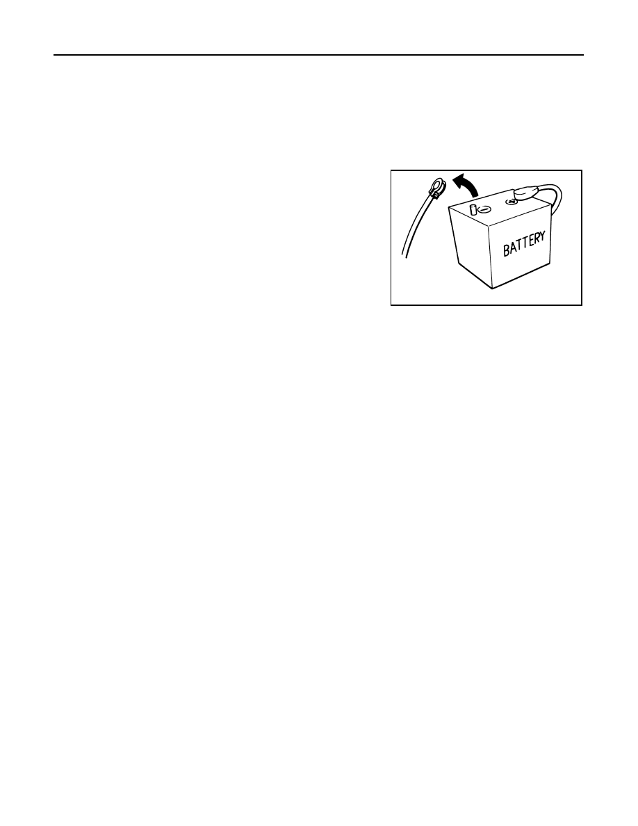
• When disconnecting the 12V battery terminal, turn off the ACC

power before disconnecting the 12V battery terminal, observing
“How to disconnect 12V battery terminal” described below.
NOTE:
Some ECUs operate for a certain fixed time even after ignition
switch is turned OFF and ignition power supply is stopped. If the
battery terminal is disconnected before ECU stops, accidental DTC
detection or ECU data damage may occur.

•  For vehicles with the 2-batteries, be sure to connect the main bat-

tery and the sub battery before turning ON the ignition switch.
NOTE:
If the ignition switch is turned ON with any one of the terminals of
main battery and sub battery disconnected, then DTC may be detected.

•  After installing the 12V battery, always check "Self Diagnosis Result" of all ECUs and erase DTC.

NOTE:
The removal of 12V battery may cause a DTC detection error.

HOW TO DISCONNECT 12V BATTERY TERMINAL

Disconnect 12V battery terminal according to Instruction 1 or Instruction 2 described below.
For vehicles parked by ignition switch OFF, refer to Instruction 2.

INSTRUCTION 1

1.

Open the hood.

2.

Turn key switch to the OFF position with the driver side door opened.

3.

Get out of the vehicle and close the driver side door.

4.

Wait at least 3 minutes. For vehicle with the engine listed below, remove the battery terminal after a lapse
of the specified time.

CAUTION:

While waiting, never operate the vehicle such as locking, opening, and closing doors. Violation of
this caution results in the activation of ACC power supply according to the Auto ACC function.

5.

Remove 12V battery terminal.

CAUTION:

After installing 12V battery, always check self-diagnosis results of all ECUs and erase DTC.

INSTRUCTION 2 (FOR VEHICLES PARKED BY IGNITION SWITCH OFF)

1.

Unlock the door with intelligent key or remote keyless entry.
NOTE:
At this moment, ACC power is supplied.

2.

Open the driver side door.

3.

Open the hood.

4.

Close the driver side door.

5.

Wait at least 3 minutes.

SEF289H

D4D engine

: 20 minutes

HRA2DDT

: 12 minutes

K9K engine

: 4 minutes

M9R engine

: 4 minutes

R9M engine

: 4 minutes

V9X engine

: 4 minutes

PRECAUTIONS

BRM-385

< PRECAUTION >

[EXCEPT FOR EUROPE AND RUSSIA (RHD)]

C

D

E

F

G

H

I

J

L

M

A

B

BRM

N

O

P

CAUTION:

While waiting, never operate the vehicle such as locking, opening, and closing doors. Violation of
this caution results in the activation of ACC power supply according to the Auto ACC function.

6.

Remove 12V battery terminal.

CAUTION:

After installing 12V battery, always check self-diagnosis results of all ECUs and erase DTC.

BRM-386

< PRECAUTION >

[EXCEPT FOR EUROPE AND RUSSIA (RHD)]

REPAIRING HIGH STRENGTH STEEL

REPAIRING HIGH STRENGTH STEEL

High Strength Steel (HSS)

INFOID:0000000010499147

High strength steel is used for body panels in order to reduce vehicle weight.
Accordingly, precautions in repairing automotive bodies made of high strength steel are described below:

Tensile strength

Major applicable parts

440 - 780 MPa

• Trans control reinforcement

(Center front floor assembly component part) 

• 2nd crossmember

(Front floor assembly component part) 

• 3rd crossmember

(Front floor assembly component part) 

• 3rd crossmember reinforcement

(Front floor assembly component part) 

• Lower dash crossmember

(Lower dash assembly component part) 

• Side dash

(Side dash assembly component part) 

• Inner front pillar reinforcement

(Side dash assembly component part) 

• Front suspension spring support

(Front strut housing assembly component part) 

• Engine mounting bracket reinforcement

(Front strut housing assembly component part) 

• Engine mounting bracket

(Front strut housing assembly component part) 

• Front bumper reinforcement assembly
• Lower front bumper stay 
• Front side member closing plate (Front)

(Side member closing plate assembly component part) 

• Outer add on frame bracket

(Side member closing plate assembly component part) 

• Closing plate reinforcement

(Side member closing plate assembly component part) 

• Front side member assembly
• Engine mounting member bracket assembly
• Front suspension mounting rear bracket assembly
• Inner sill extension

(Rear side member assembly component part) 

• Inner rear sill

(Rear side member assembly component part) 

• Outer rear anchor reinforcement

(Rear side member assembly component part) 

• Rear side member extension assembly
• Inner front side roof rail assembly
• Upper inner front pillar assembly
• Inner center pillar (Lower)

(Inner center pillar assembly component part) 

• Lower front pillar hinge brace
• Rear bumper stay assembly

REPAIRING HIGH STRENGTH STEEL

BRM-387

< PRECAUTION >

[EXCEPT FOR EUROPE AND RUSSIA (RHD)]

C

D

E

F

G

H

I

J

L

M

A

B

BRM

N

O

P

Read the following precautions when repairing HSS:

1.

Additional points to consider
• The repair of reinforcements (such as side members) by heat-

ing is not recommended, because it may weaken the compo-
nent. When heating is unavoidable, never heat HSS parts
above 550

°

C (1,022

°

F).

Verify heating temperature with a thermometer.
(Crayon-type and other similar type thermometer are appropri-
ate.)

• When straightening body panels, use caution in pulling any HSS panel. Because HSS is very strong,

pulling may cause deformation in adjacent sections of the body. In this case, increase the number of
measuring points, and carefully pull the HSS panel.

• When cutting HSS panels, avoid gas (torch) cutting if possible.

Instead, use a saw to avoid weakening surrounding areas due
to heat. If gas (torch) cutting is unavoidable, allow a minimum
margin of 50 mm (1.97 in).

Tensile strength

Major applicable parts

980 - 1350 MPa

• Front side member rear extension

(Front floor assembly component part) 

• Inner sill assembly
• Lower center dash crossmember assembly
• Front bumper reinforcement assembly
• Front side member closing plate (Rear)

(Side member closing plate assembly component part) 

• Front side member (Rear)

(Front side member assembly component part) 

• Inner center pillar (Upper)

(Inner center pillar assembly component part) 

• Outer side roof rail
• Center pillar hinge brace (Upper)

(Center pillar hinge brace assembly component part) 

• Outer front pillar reinforcement

(Front pillar hinge brace assembly component part) 

• Outer sill reinforcement

(Outer sill reinforcement assembly component part) 

• Rear bumper reinforcement assembly

PIIA0115E

PIIA0117E


Content   ..  1637  1638  1639  1640   ..