Nissan Qashqai J11. Manual - part 163


  Index      Nissan     Nissan Qashqai J11 - Service and Repair Manual


Search            


Content   ..  161  162  163  164   ..


Nissan Qashqai J11. Manual - part 163


CO-56

< SERVICE DATA AND SPECIFICATIONS (SDS) 

[MR20DD]

SERVICE DATA AND SPECIFICATIONS (SDS)

SERVICE DATA AND SPECIFICATIONS (SDS)

SERVICE DATA AND SPECIFICATIONS (SDS)

Periodical Maintenance Specification

INFOID:0000000010665094

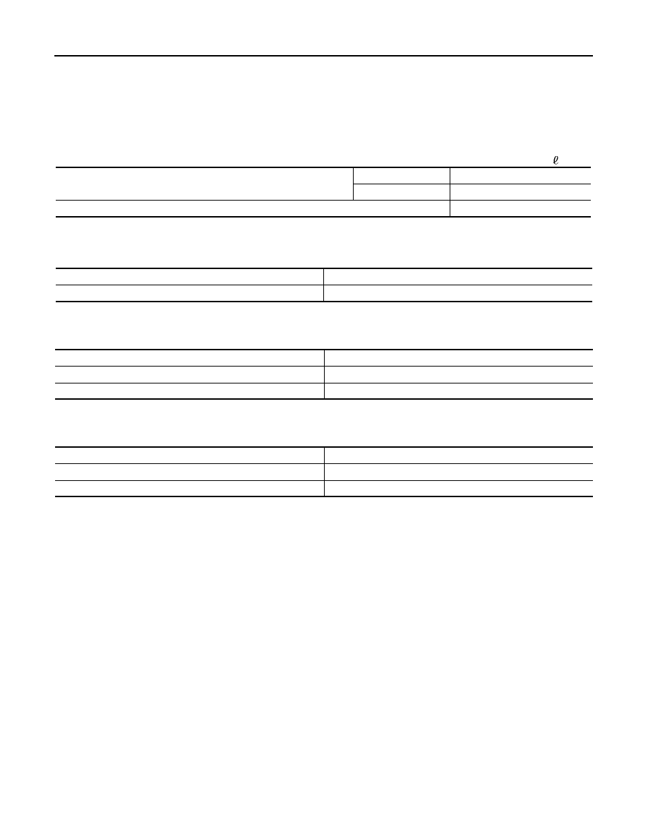
ENGINE COOLANT CAPACITY (APPROXIMATE)

Unit: 

 (Imp qt)

Radiator

INFOID:0000000010665095

Unit: kPa (bar, kg/cm

2

, psi)

Thermostat

INFOID:0000000010665096

Standard

Water Control Valve

INFOID:0000000010665097

Standard

Engine coolant capacity (With reservoir tank at “MAX” level)

CVT models

7.4 (6-1/2)

M/T models

7.1 (6-1/4)

Reservoir tank engine coolant capacity (At “MAX” level)

0.8 (3/4)

Reservoir tank cap relief pressure

140 (1.4, 1.4, 20)

Leakage testing pressure

140 (1.4, 1.4, 20)

Valve opening temperature

80.5 - 83.5

°

C (177 - 182

°

F)

Maximum valve lift

8.0 mm/95

°

C (0.315 in/203

°

F)

Valve closing temperature

77

°

C (171

°

F)

Valve opening temperature

93.5 - 96.5

°

C (200 - 206

°

F)

Maximum valve lift

8.0 mm/108

°

C (0.315 in/226

°

F)

Valve closing temperature

90

°

C (194

°

F)

PRECAUTIONS

CO-57

< PRECAUTION >

[K9K]

C

D

E

F

G

H

I

J

K

L

M

A

CO

N

P

O

PRECAUTION

PRECAUTIONS

Precautions for Removing Battery Terminal

INFOID:0000000010508566

• With the adoption of Auto ACC function, ACC power is automatically supplied by operating the intelligent key

or remote keyless entry or by opening/closing the driver side door. In addition, ACC power is supplied even
after the ignition switch is turned to the OFF position, i.e. ACC power is supplied for a certain fixed time.

• When disconnecting the 12V battery terminal, turn off the ACC

power before disconnecting the 12V battery terminal, observing
“How to disconnect 12V battery terminal” described below.
NOTE:
Some ECUs operate for a certain fixed time even after ignition
switch is turned OFF and ignition power supply is stopped. If the
battery terminal is disconnected before ECU stops, accidental DTC
detection or ECU data damage may occur.

•  For vehicles with the 2-batteries, be sure to connect the main bat-

tery and the sub battery before turning ON the ignition switch.
NOTE:
If the ignition switch is turned ON with any one of the terminals of
main battery and sub battery disconnected, then DTC may be detected.

•  After installing the 12V battery, always check "Self Diagnosis Result" of all ECUs and erase DTC.

NOTE:
The removal of 12V battery may cause a DTC detection error.

HOW TO DISCONNECT 12V BATTERY TERMINAL

Disconnect 12V battery terminal according to Instruction 1 or Instruction 2 described below.
For vehicles parked by ignition switch OFF, refer to Instruction 2.

INSTRUCTION 1

1.

Open the hood.

2.

Turn key switch to the OFF position with the driver side door opened.

3.

Get out of the vehicle and close the driver side door.

4.

Wait at least 3 minutes. For vehicle with the engine listed below, remove the battery terminal after a lapse
of the specified time.

CAUTION:

While waiting, never operate the vehicle such as locking, opening, and closing doors. Violation of
this caution results in the activation of ACC power supply according to the Auto ACC function.

5.

Remove 12V battery terminal.

CAUTION:

After installing 12V battery, always check self-diagnosis results of all ECUs and erase DTC.

INSTRUCTION 2 (FOR VEHICLES PARKED BY IGNITION SWITCH OFF)

1.

Unlock the door with intelligent key or remote keyless entry.
NOTE:
At this moment, ACC power is supplied.

2.

Open the driver side door.

3.

Open the hood.

4.

Close the driver side door.

5.

Wait at least 3 minutes.

SEF289H

D4D engine

: 20 minutes

HRA2DDT

: 12 minutes

K9K engine

: 4 minutes

M9R engine

: 4 minutes

R9M engine

: 4 minutes

V9X engine

: 4 minutes

CO-58

< PRECAUTION >

[K9K]

PRECAUTIONS

CAUTION:

While waiting, never operate the vehicle such as locking, opening, and closing doors. Violation of
this caution results in the activation of ACC power supply according to the Auto ACC function.

6.

Remove 12V battery terminal.

CAUTION:

After installing 12V battery, always check self-diagnosis results of all ECUs and erase DTC.

Precaution for Supplemental Restraint System (SRS) "AIR BAG" and "SEAT BELT 
PRE-TENSIONER"

INFOID:0000000010416367

The Supplemental Restraint System such as “AIR BAG” and “SEAT BELT PRE-TENSIONER”, used along
with a front seat belt, helps to reduce the risk or severity of injury to the driver and front passenger for certain
types of collision. Information necessary to service the system safely is included in the “SRS AIR BAG” and
“SEAT BELT” of this Service Manual.

The vehicle may be equipped with a passenger air bag deactivation switch. Because no rear seat exists where
a rear-facing child restraint can be placed, the switch is designed to turn off the passenger air bag so that a
rear-facing child restraint can be used in the front passenger seat. The switch is located in the center of the
instrument panel, near the ashtray. When the switch is turned to the ON position, the passenger air bag is
enabled and could inflate for certain types of collision. When the switch is turned to the OFF position, the pas-
senger air bag is disabled and will not inflate. A passenger air bag OFF indicator on the instrument panel lights
up when the passenger air bag is switched OFF. The driver air bag always remains enabled and is not affected
by the passenger air bag deactivation switch.

WARNING:

Always observe the following items for preventing accidental activation.
• To avoid rendering the SRS inoperative, which could increase the risk of personal injury or death in

the event of a collision that would result in air bag inflation, all maintenance must be performed by
an authorized NISSAN/INFINITI dealer.

• Improper maintenance, including incorrect removal and installation of the SRS, can lead to personal

injury caused by unintentional activation of the system. For removal of Spiral Cable and Air Bag
Module, see the “SRS AIR BAG”.

• Do not use electrical test equipment on any circuit related to the SRS unless instructed to in this

Service Manual. SRS wiring harnesses can be identified by yellow and/or orange harnesses or har-
ness connectors.

• The vehicle may be equipped with a passenger air bag deactivation switch which can be operated by

the customer. When the passenger air bag is switched OFF, the passenger air bag is disabled and
will not inflate. When the passenger air bag is switched ON, the passenger air bag is enabled and
could inflate for certain types of collision. After SRS maintenance or repair, make sure the passenger
air bag deactivation switch is in the same position (ON or OFF) as when the vehicle arrived for ser-
vice.

PRECAUTIONS WHEN USING POWER TOOLS (AIR OR ELECTRIC) AND HAMMERS

WARNING:

Always observe the following items for preventing accidental activation.
• When working near the Air Bag Diagnosis Sensor Unit or other Air Bag System sensors with the

ignition ON or engine running, DO NOT use air or electric power tools or strike near the sensor(s)
with a hammer. Heavy vibration could activate the sensor(s) and deploy the air bag(s), possibly
causing serious injury.

• When using air or electric power tools or hammers, always switch the ignition OFF, disconnect the

battery, and wait at least 3 minutes before performing any service.

Precaution Necessary for Steering Wheel Rotation after Battery Disconnect

INFOID:0000000010416368

NOTE:
• Before removing and installing any control units, first turn the ignition switch to the LOCK position, then dis-

connect both battery cables.

• After finishing work, confirm that all control unit connectors are connected properly, then re-connect both

battery cables.

PRECAUTIONS

CO-59

< PRECAUTION >

[K9K]

C

D

E

F

G

H

I

J

K

L

M

A

CO

N

P

O

• Always use CONSULT to perform self-diagnosis as a part of each function inspection after finishing work. If

a DTC is detected, perform trouble diagnosis according to self-diagnosis results.

For vehicle with steering lock unit, if the battery is disconnected or discharged, the steering wheel will lock and
cannot be turned.
If turning the steering wheel is required with the battery disconnected or discharged, follow the operation pro-
cedure below before starting the repair operation.

OPERATION PROCEDURE

1.

Connect both battery cables.
NOTE:
Supply power using jumper cables if battery is discharged.

2.

Turn the ignition switch to ACC position.
(At this time, the steering lock will be released.)

3.

Disconnect both battery cables. The steering lock will remain released with both battery cables discon-
nected and the steering wheel can be turned.

4.

Perform the necessary repair operation.

5.

When the repair work is completed, re-connect both battery cables. With the brake pedal released, turn
the ignition switch from ACC position to ON position, then to LOCK position. (The steering wheel will lock
when the ignition switch is turned to LOCK position.)

6.

Perform self-diagnosis check of all control units using CONSULT.

Precaution for Liquid Gasket

INFOID:0000000010416369

REMOVAL OF LIQUID GASKET

• After removing the mounting bolts and nuts, separate the mating

surface using a seal cutter and remove the liquid gasket.

CAUTION:

Never damage the mating surfaces.

• In areas where the cutter is difficult to use, use a plastic hammer to

lightly tap the gasket applied area.

CAUTION:

If for some unavoidable reason a tool such as a flat-bladed
screwdriver is used, be careful not to damage the mating sur-
faces.

LIQUID GASKET APPLICATION PROCEDURE 

1.

Using a scraper, remove the old liquid gasket adhering to the
gasket application surface and the mating surface.
• Remove the liquid gasket completely from the groove of the

gasket application surface, mounting bolts and bolt holes.

2.

Wipe the gasket application surface and the mating surface with
white gasoline (lighting and heating use) to remove adhering
moisture, grease and foreign materials.

3.

Attach the liquid gasket to the tube presser.
Use Genuine Liquid Gasket or equivalent.

PBIC0275E

PBIC0003E


Content   ..  161  162  163  164   ..