Content .. 1491 1492 1493 1494 ..
Nissan Qashqai J11. Manual - part 1493
POWER SUPPLY AND GROUND CIRCUIT
SEC-271
< DTC/CIRCUIT DIAGNOSIS >
[WITHOUT INTELLIGENT KEY SYSTEM]
C
D
E
F
G
H
I
J
L
M
A
B
SEC
N
O
P
POWER SUPPLY AND GROUND CIRCUIT
SIREN CONTROL UNIT
SIREN CONTROL UNIT : Diagnosis Procedure
INFOID:0000000010479798
1.
CHECK FUSE
Check that the following fuse is not blown.
Is the fuse fusing?
YES
>> Replace the blown fuse after repairing the affected circuit if a fuse is blown.
NO
>> GO TO 2.
2.
CHECK POWER SUPPLY CIRCUIT
1.
Turn ignition switch OFF.
2.
Disconnect siren control unit connector.
3.
Check voltage between siren control unit harness connector and the ground.
Is the inspection result normal?
YES
>> GO TO 3.
NO
>> Repair or replace harness.
3.
CHECK GROUND CIRCUIT
Check continuity between siren control unit harness connectors and the ground.
Is the inspection result normal?
YES
>> INSPECTION END
NO
>> Repair or replace harness.
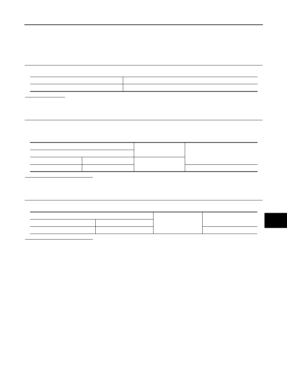
Signal name
Fuse
Battery power supply
20 (5 A)
(+)
(
−
)
Voltage
(Approx.)
Siren control unit
Connector
Terminal
Ground
B27
2
Battery voltage
Siren control unit
Ground
Continuity
Connector
Terminal
B27
5
Existed