Content .. 1448 1449 1450 1451 ..
Nissan Qashqai J11. Manual - part 1450
B2198 NATS ANTENNA AMP.
SEC-99
< DTC/CIRCUIT DIAGNOSIS >
[WITH INTELLIGENT KEY SYSTEM]
C
D
E
F
G
H
I
J
L
M
A
B
SEC
N
O
P
Is the inspection result normal?
YES
>> Replace NATS antenna amp. Refer to
SEC-187, "Removal and Installation"
.
NO
>> GO TO 2.
2.
CHECK NATS ANTENNA AMP. COMMUNICATION SIGNAL CIRCUIT
1.
Disconnect BCM connector.
2.
Check continuity between NATS antenna amp. harness connector and BCM harness connector.
Is the inspection result normal?
YES
>> GO TO 3.
NO
>> Repair or replace harness.
3.
REPLACE BCM
BCS-135, "Removal and Installation"
.
>> INSPECTION END
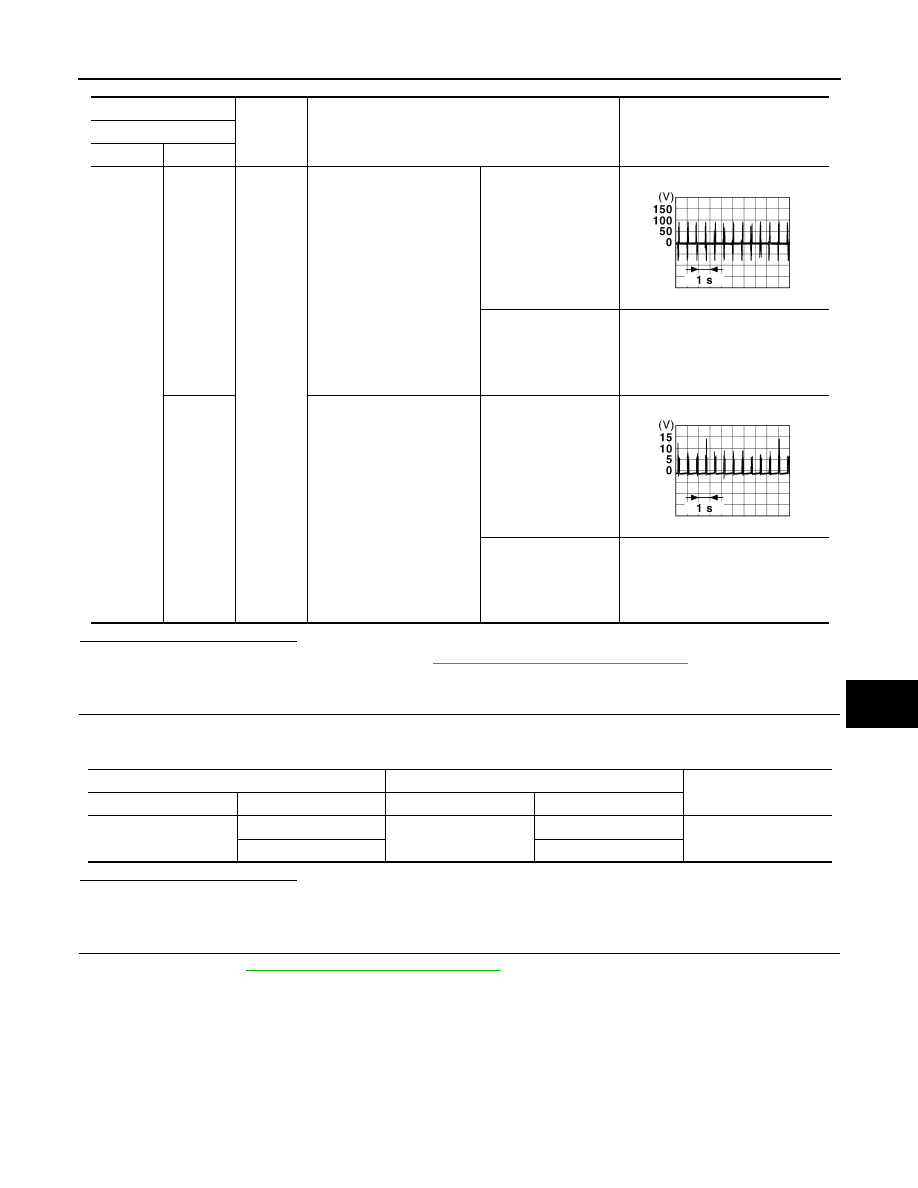
(+)
(–)
Condition
Voltage (V)
NATS antenna amp.
Connector
Terminal
M91
1
Ground
Intelligent Key: Intelligent
Key battery is removed.
Intelligent Key back
side is contacted to
push-button ignition
switch, turn ignition
switch ON.
Intelligent Key back
side is not contacted
to push-button ignition
switch, turn ignition
switch ON.
0V
2
Intelligent Key: Intelligent
Key battery is removed.
Intelligent Key back
side is contacted to
push-button ignition
switch, turn ignition
switch ON.
Intelligent Key back
side is not contacted
to push-button ignition
switch, turn ignition
switch ON.
0V
JMMIA1650GB
JMMIA1651GB
NATS antenna amp.
BCM
Continuity
Connector
Terminal
Connector
Terminal
M91
1
M69
115
Existed
2
114