Nissan Qashqai J11. Manual - part 1430


  Index      Nissan     Nissan Qashqai J11 - Service and Repair Manual


Search            


Content   ..  1428  1429  1430  1431   ..


Nissan Qashqai J11. Manual - part 1430


SYSTEM

SEC-19

< SYSTEM DESCRIPTION >

[WITH INTELLIGENT KEY SYSTEM]

C

D

E

F

G

H

I

J

L

M

A

B

SEC

N

O

P

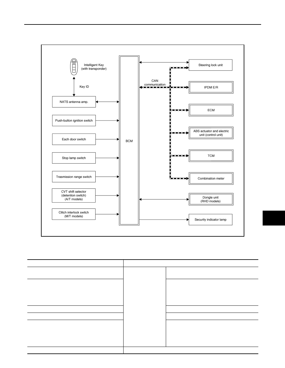
NISSAN ANTI-THEFT SYSTEM : System Description

INFOID:0000000010337875

SYSTEM DIAGRAM

BCM INPUT/OUTPUT SIGNAL CHART

Input Signal Item

JMKIB3225GB

Transmit unit

Signal name

ECM

CAN communication

• Engine status signal
• Starter control relay request signal

IPDM E/R

• Push-button ignition switch status signal
• Ignition ON signal
• Starter relay/Starter control relay status signal
• Starter control relay status signal
• Neutral position signal

Combination meter

Vehicle speed signal (Meter)

ABS actuator and electric unit (control unit)

Vehicle speed signal (ABS)

Steering lock unit

• Steering lock unit lock status signal
• Steering lock unit unlock status signal
• Lock/unlock position signal
• Steering lock undefined position signal
• Steering lock wrong code signal

NATS antenna amp.

Key ID signal

SEC-20

< SYSTEM DESCRIPTION >

[WITH INTELLIGENT KEY SYSTEM]

SYSTEM

Output Signal Item

SYSTEM DESCRIPTION

• The Nissan Anti-Theft System (NATS) prevents the engine from being started by Intelligent Key whose ID is

not registered to the vehicle (BCM). It has higher protection against auto theft involving the duplication of
mechanical keys.

• The ignition key integrated in the Intelligent Key cannot start the engine. When the Intelligent Key battery is

discharged, the NATS ID verification is performed between the transponder integrated with Intelligent Key
and BCM via NATS antenna amp. when the Intelligent Key backside is contacted to push-button ignition
switch while brake pedal is depressed. If the verification result is OK, the engine start operation can be per-
formed by the push-button ignition switch operation.

• Locate the security indicator lamp and always blinks it when the ignition switch is in any position except ON

to warn that the vehicle is equipped with Nissan Anti-Theft System (NATS).

• Up to 4 Intelligent Keys can be registered (including the standard ignition key) upon request from the owner.
• When replacing ECM, BCM or Intelligent Key, the specified procedure (Initialization and registration) using

CONSULT is required.

PRECAUTIONS FOR KEY REGISTRATION

The ID registration is a procedure that erases the current NATS ID once, and then registers a new ID. There-
fore before starting the registration operation, collect all registered Intelligent Keys from the customer.

SECURITY INDICATOR LAMP

• Security indicator lamp warns that the vehicle is equipped with NATS.
• Security indicator lamp always blinks when the ignition switch is in any position other than ON.

NOTE:
Because security indicator lamp is highly efficient, the battery is barely affected.

ENGINE START OPERATION WHEN INTELLIGENT KEY IS CONTACTED TO PUSH-BUTTON IG-
NITION SWITCH

1.

When brake pedal is depressed while selector lever is in the P position (CVT models), or shift lever is in
the Neutral position (M/T models), BCM activates NATS antenna amp. that is located behind push-button
ignition switch.

2.

When Intelligent Key (transponder built-in) backside is contacted to push-button ignition switch, BCM
starts NATS ID verification between BCM and Intelligent Key (transponder built-in) via NATS antenna
amp.

3.

When NATS ID verification result is OK, buzzer in combination meter sounds.

4.

When push-button ignition switch is pressed, BCM transmits steering lock unit unlock request signal to
steering lock unit.
• Lock/unlock position signal
• Steering lock unit lock status signal
• Steering lock undefined position signal

Push-button ignition switch

Push-button ignition switch operation signal

Each door switch

Door open/close condition signal

Stop lamp switch

Brake pedal operation signal

CVT shift selector (detention switch) (CVT models)

P position signal

Transmission range switch (CVT models)

P/N position signal

Reverse/neutral position switch (M/T models)

Neutral position signal

Clutch interlock switch (M/T models)

Clutch interlock switch signal

Transmit unit

Signal name

Reception unit

Signal name

IPDM E/R

CAN communication

Ignition ON signal

Combination meter

Security indicator lamp signal

Steering lock unit

• Steering lock unit unlock request signal
• Steering lock unit lock request signal
• Steering lock code signal
• Ignition ON signal

SYSTEM

SEC-21

< SYSTEM DESCRIPTION >

[WITH INTELLIGENT KEY SYSTEM]

C

D

E

F

G

H

I

J

L

M

A

B

SEC

N

O

P

• Steering lock wrong code signal

5.

When BCM receives a steering lock unit unlock status signal from the steering lock unit, it stops the steer-
ing lock unit unlock request signal.

6.

When the ignition switch is turned to ON, BCM performs ID verification with the ECM. When the result is
OK, engine start is permitted.

7.

BCM detects that the selector lever position and brake pedal operation condition.

8.

When ECM detects that the start engine conditions* are satisfied, it transmits a starter control relay
request signal to BCM.

9.

When BCM receives a starter control relay request signal from ECM, the starter control relay is turned
ON.

10. When starter control relay is turned ON, IPDM E/R turns ON the starter relay and drives the starter motor.

11. When BCM receives an engine status signal from ECM, it turns the starter relay and starter control relay

OFF and stops cranking.

*: For the engine start condition, refer to “IGNITION SWITCH POSITION CHANGE TABLE BY PUSH-BUT-
TON IGNITION SWITCH OPERATION” below.

IGNITION SWITCH POSITION CHANGE TABLE BY PUSH-BUTTON IGNITION SWITCH OPERA-
TION

The ignition switch position can be changed by the following operations.
NOTE:
• When an Intelligent Key is within the detection area of inside key antenna or when Intelligent Key backside is

contacted to push-button ignition switch, it is equivalent to the operations below.

• When starting the engine, the BCM monitors under the engine start conditions,

CVT models

- Brake pedal operation condition
- Selector lever position
- Vehicle speed

M/T models

- Clutch pedal operation condition
- Vehicle speed

Vehicle speed: less than 4 km/h (2.5 MPH)

Vehicle speed: 4 km/h (2.5 MPH) or more

Emergency stop operation

Power supply posi-

tion

Condition

Push-button ignition 

switch operation fre-

quency

CVT models

M/T models

Selector lever

Brake pedal oper-

ation condition

Shift lever position

Clutch pedal oper-

ation condition

LOCK 

 ON

Not depressed

Not depressed

1

LOCK 

 ON 

 OFF

Not depressed

Not depressed

2

LOCK 

 START

ON 

 START

P or N position

Depressed

Depressed

1

Engine is running 


LOCK

1

Power supply posi-

tion

Condition

Push-button ignition 

switch operation fre-

quency

CVT models

M/T models

Selector lever

Brake pedal oper-

ation condition

Shift lever position

Clutch pedal oper-

ation condition

Engine is running 


OFF 

Emergency stop oper-

ation

Engine stall return 
operation while driv-
ing 

N position

Not depressed

Depressed

1

SEC-22

< SYSTEM DESCRIPTION >

[WITH INTELLIGENT KEY SYSTEM]

SYSTEM

• Press and hold the push-button ignition switch for 2 seconds or more.

• Press the push-button ignition switch 3 times or more within 1.5 seconds.

VEHICLE SECURITY SYSTEM

VEHICLE SECURITY SYSTEM : System Description

INFOID:0000000010437576

SYSTEM DIAGRAM

BCM INPUT/OUTPUT SIGNAL CHART

Input Signal Item

Output Signal Item

JMKIB3226GB

Transmit unit

Signal name

IPDM E/R

CAN communication

Hood switch signal

Push-button ignition switch

Push switch signal

Each door switch

Door switch signal

Each door request switch

Door request switch signal

Siren control unit

Alarm link signal

Sensor cancel switch

Sensor cancel switch signal


Content   ..  1428  1429  1430  1431   ..