Content .. 1287 1288 1289 1290 ..
Nissan Qashqai J11. Manual - part 1289
DOOR LOCK ACTUATOR
DLK-425
< DTC/CIRCUIT DIAGNOSIS >
[TYPE 3]
C
D
E
F
G
H
I
J
L
M
A
B
DLK
N
O
P
Is the inspection result normal?
YES
>> Door lock actuator is OK.
NO
>> Refer to
DLK-421, "DRIVER SIDE : Diagnosis Procedure"
.
REAR RH : Diagnosis Procedure
INFOID:0000000010499809
1.
CHECK DOOR LOCK ACTUATOR INPUT SIGNAL
1.
Turn ignition switch OFF.
2.
Disconnect rear door lock assembly RH connector.
3.
Check voltage between rear door lock assembly RH harness connector and ground.
Is the inspection result normal?
YES
>> Replace rear door lock assembly RH.
NO
>> GO TO 2.
2.
CHECK DOOR LOCK ACTUATOR CIRCUIT
1.
Disconnect BCM connector and all door lock assembly connector.
2.
Check continuity between BCM harness connector and rear door lock assembly RH harness connector.
3.
Check continuity between BCM harness connector and ground.
Is the inspection result normal?
YES
>> GO TO 3.
NO
>> Repair or replace harness.
3.
CHECK BCM OUTPUT SIGNAL
1.
Connect BCM connector.
2.
Check voltage between BCM harness connector and ground.
Is the inspection result normal?
YES
>> Check for internal short of each door lock actuator.
NO
>> Replace BCM. Refer to
BCS-135, "Removal and Installation"
.
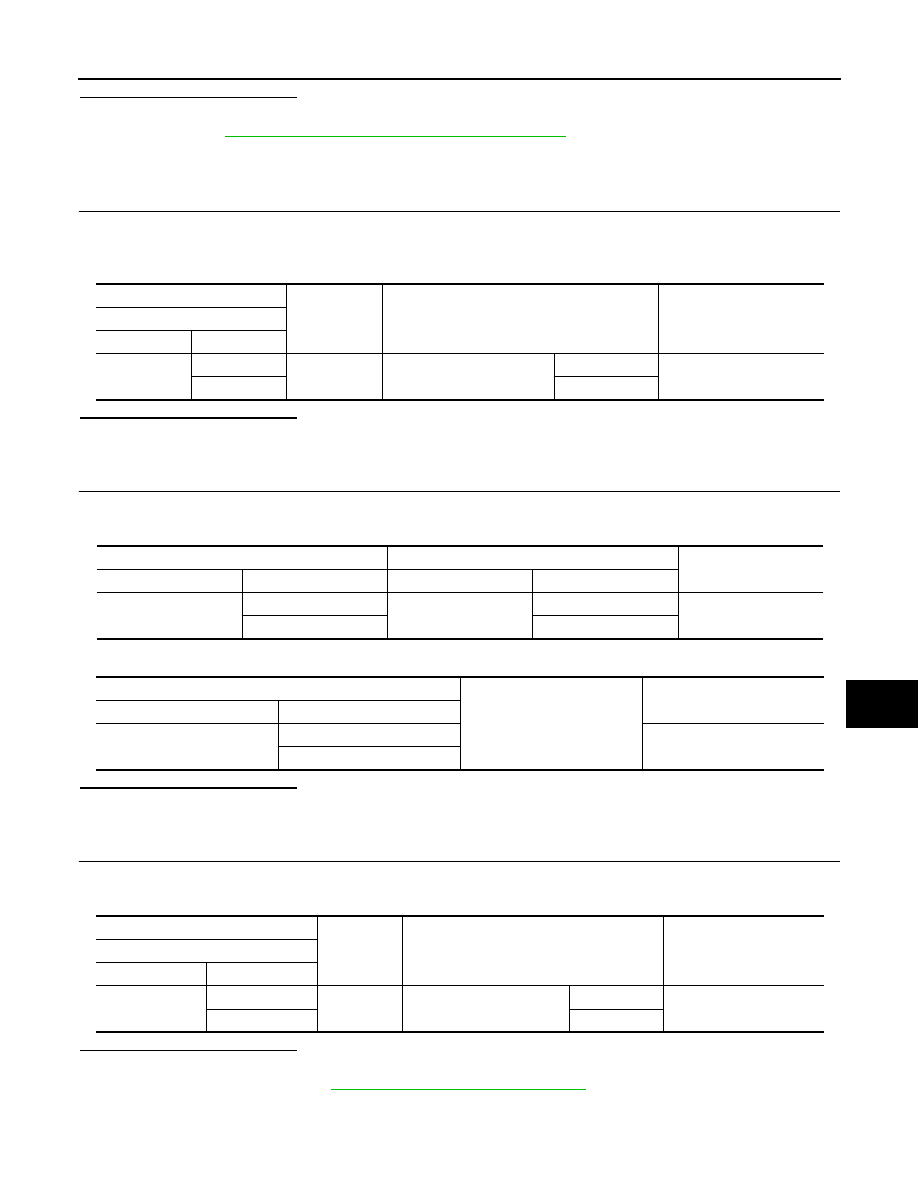
(+)
(–)
Condition
Voltage
Rear door lock assembly RH
Connector
Terminal
D65
2
Ground
Door lock and unlock switch
Unlock
9 – 16 V
3
Lock
BCM
Rear door lock assembly RH
Continuity
Connector
Terminal
Connector
Terminal
B3
124
D65
2
Existed
125
3
BCM
Ground
Continuity
Connector
Terminal
B3
124
Not existed
125
(+)
(–)
Condition
Voltage
BCM
Connector
Terminal
B3
124
Ground
Door lock and unlock switch
Unlock
9 – 16 V
125
Lock