Content .. 1250 1251 1252 1253 ..
Nissan Qashqai J11. Manual - part 1252
DOOR LOCK ACTUATOR
DLK-277
< DTC/CIRCUIT DIAGNOSIS >
[TYPE 2]
C
D
E
F
G
H
I
J
L
M
A
B
DLK
N
O
P
Is the inspection result normal?
YES
>> GO TO 3.
NO
>> Repair or replace harness.
3.
CHECK BCM OUTPUT SIGNAL
1.
Connect BCM connector.
2.
Check voltage between BCM harness connector and ground.
Is the inspection result normal?
YES
>> Check for internal short of each door lock actuator.
NO
>> Replace BCM. Refer to
BCS-135, "Removal and Installation"
.
REAR RH
REAR RH : Component Function Check
INFOID:0000000010487298
1.
CHECK FUNCTION
1.
Select “DOOR LOCK” of “BCM” using CONSULT.
2.
Select “DOOR LOCK” in “ACTIVE TEST” mode.
3.
Check that the function operates normally according to the following conditions.
Is the inspection result normal?
YES
>> Door lock actuator is OK.
NO
>> Refer to
DLK-273, "DRIVER SIDE : Diagnosis Procedure"
.
REAR RH : Diagnosis Procedure
INFOID:0000000010487299
1.
CHECK DOOR LOCK ACTUATOR INPUT SIGNAL
1.
Turn ignition switch OFF.
2.
Disconnect rear door lock assembly RH connector.
3.
Check voltage between rear door lock assembly RH harness connector and ground.
Is the inspection result normal?
YES
>> Replace rear door lock assembly RH.
NO
>> GO TO 2.
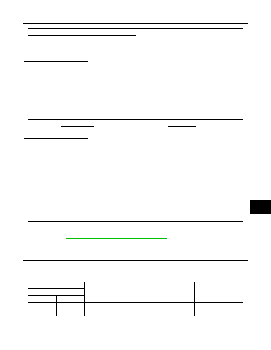
BCM
Ground
Continuity
Connector
Terminal
B3
124
Not existed
125
(+)
(–)
Condition
Voltage
BCM
Connector
Terminal
B3
124
Ground
Door lock and unlock switch
Unlock
9 – 16 V
125
Lock
Monitor item
Status
DOOR LOCK
ALL LOCK
Door lock actuators
LOCK
ALL UNLOCK
UNLOCK
(+)
(–)
Condition
Voltage
Rear door lock assembly RH
Connector
Terminal
D64
2
Ground
Door lock and unlock switch
Unlock
9 – 16 V
3
Lock