Nissan Qashqai J11. Manual - part 1249


  Index      Nissan     Nissan Qashqai J11 - Service and Repair Manual


Search            


Content   ..  1247  1248  1249  1250   ..


Nissan Qashqai J11. Manual - part 1249


B2622 INSIDE ANTENNA

DLK-265

< DTC/CIRCUIT DIAGNOSIS >

[TYPE 2]

C

D

E

F

G

H

I

J

L

M

A

B

DLK

N

O

P

Is the inspection result normal?

YES

>> GO TO 3.

NO

>> Repair or replace harness.

3.

CHECK INSIDE KEY ANTENNA INPUT SIGNAL 2

1.

Replace inside key antenna (luggage room). (New antenna or other antenna)

2.

Connect BCM connector and inside key antenna (luggage room) connector.

3.

Turn ignition switch ON.

4.

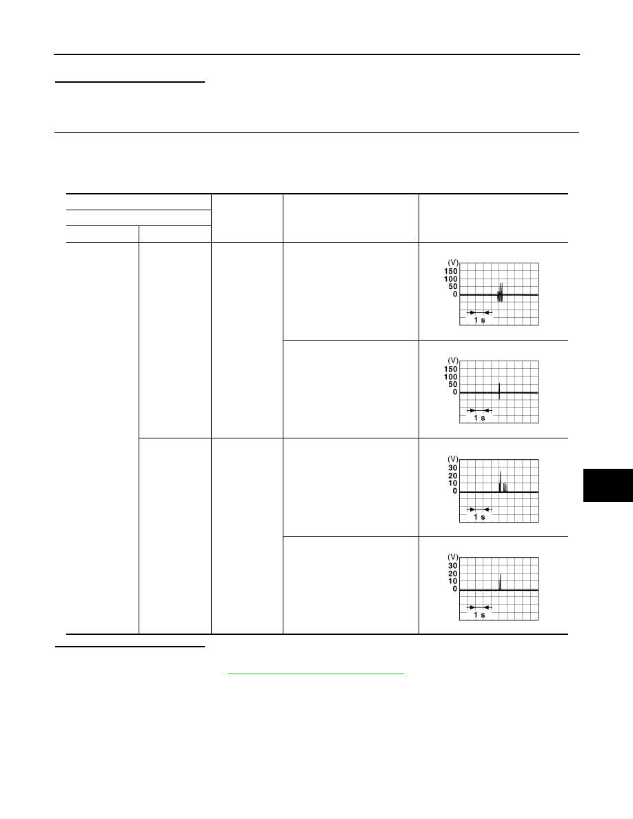
Check signal between BCM harness connector and ground using oscilloscope.

Is the inspection result normal?

YES

>> Replace inside key antenna (luggage room).

NO

>> Replace BCM. Refer to 

BCS-135, "Removal and Installation"

.

(+)

(–)

Condition

Signal

(Reference value)

BCM

Connector

Terminal

B4

22

Ground

When Intelligent Key is not in the 
antenna detection area

When Intelligent Key is in the an-
tenna detection area

23

Ground

When Intelligent Key is not in the 
antenna detection area

When Intelligent Key is in the an-
tenna detection area

JMMIA1652GB

JMMIA1653GB

JSMIA1507GB

JSMIA1506GB

DLK-266

< DTC/CIRCUIT DIAGNOSIS >

[TYPE 2]

BACK DOOR OPENER ACTUATOR

BACK DOOR OPENER ACTUATOR

Component Function Check

INFOID:0000000010487282

1.

CHECK FUNCTION

1.

Select “INTELLIGENT KEY” of “BCM” using CONSULT.

2.

Select “TRUNK/BACK DOOR” in “ACTIVE TEST” mode.

3.

Check that the function operates normally according to the following conditions.

Is the inspection result normal?

YES

>> Back door opener actuator is OK.

NO

>> Refer to 

DLK-266, "Diagnosis Procedure"

.

Diagnosis Procedure

INFOID:0000000010487283

1.

CHECK BACK DOOR OPENER ACTUATOR INPUT SIGNAL

1.

Turn ignition switch OFF.

2.

Disconnect back door lock assembly connector.

3.

Check voltage between back door lock assembly harness connector and ground.

Is the inspection result normal?

YES

>> GO TO 3.

NO

>> GO TO 2.

2.

CHECK BACK DOOR OPENER ACTUATOR CIRCUIT

1.

Disconnect BCM connector.

2.

Check continuity between BCM harness connector and back door lock assembly harness connector. 

3.

Check continuity between BCM harness connector and ground.

Is the inspection result normal?

YES

>> Replace BCM. Refer to 

BCS-135, "Removal and Installation"

.

NO

>> Repair or replace harness.

3.

CHECK BACK DOOR OPENER ACTUATOR GROUND CIRCUIT

Check continuity between back door lock assembly harness connector and ground.

Monitor item

Status

TRUNK/BACK DOOR

OPEN

Back door

OPEN

(+)

(–)

Condition

Voltage

Back door lock assembly

Connector

Terminal

B2

1

Ground

Back door 
opener switch

ON

9 - 16 V

BCM

Back door lock assembly

Continuity 

Connector

Terminal

Connector

Terminal

B3

121

B2

1

Existed

BCM

Ground

Continuity 

Connector

Terminal

B3

121

Not existed

BACK DOOR OPENER ACTUATOR

DLK-267

< DTC/CIRCUIT DIAGNOSIS >

[TYPE 2]

C

D

E

F

G

H

I

J

L

M

A

B

DLK

N

O

P

Is the inspection normal?

YES

>> Replace back door lock assembly.

NO

>> Repair or replace harness.

Back door lock assembly

Ground

Continuity

Connector

Terminal

B2

2

Existed

DLK-268

< DTC/CIRCUIT DIAGNOSIS >

[TYPE 2]

BACK DOOR OPENER SWITCH

BACK DOOR OPENER SWITCH

Component Function Check

INFOID:0000000010487284

1.

CHECK FUNCTION

1.

Select “TRUNK” of “BCM” using CONSULT.

2.

Select “BACK DOOR OPENER SW” in “DATA MONITOR” mode.

3.

Check that the function operates normally according to the following conditions.

Is the inspection result normal?

YES

>> Back door opener switch is OK.

NO

>> Refer to 

DLK-268, "Diagnosis Procedure"

.

Diagnosis Procedure

INFOID:0000000010487285

1.

CHECK BACK DOOR OPENER SWITCH INPUT SIGNAL

1.

Turn ignition switch OFF.

2.

Disconnect back door opener switch assembly connector.

3.

Check signal between back door opener switch assembly harness connector and ground.

Is the inspection result normal?

YES

>> GO TO 3.

NO

>> GO TO 2.

2.

CHECK BACK DOOR OPENER SWITCH CIRCUIT

1.

Disconnect BCM connector.

2.

Check continuity between BCM harness connector and back door opener switch assembly harness con-
nector.

3.

Check continuity between BCM harness connector and ground.

Is the inspection result normal?

YES

>> Replace BCM. Refer to 

BCS-135, "Removal and Installation"

.

NO

>> Repair or replace harness.

3.

CHECK BACK DOOR OPENER SWITCH GROUND CIRCUIT

Check continuity between back door opener switch assembly harness connector and ground.

Monitor item

Condition

Status

BACK DOOR OPENER SW

Back door opener switch

Pressed

ON

Released

OFF

(+)

(–)

Voltage

Back door opener switch assembly

Connector

Terminal 

D94

1

Ground

9 - 16 V

BCM

Back door opener switch assembly

Continuity 

Connector

Terminal

Connector

Terminal

B4

16

D94

1

Existed

BCM

Ground

Continuity 

Connector

Terminal

B4

16

Not existed


Content   ..  1247  1248  1249  1250   ..