Nissan Qashqai J11. Manual - part 1203


  Index      Nissan     Nissan Qashqai J11 - Service and Repair Manual


Search            


Content   ..  1201  1202  1203  1204   ..


Nissan Qashqai J11. Manual - part 1203


BACK DOOR REQUEST SWITCH

DLK-81

< DTC/CIRCUIT DIAGNOSIS >

[TYPE 1]

C

D

E

F

G

H

I

J

L

M

A

B

DLK

N

O

P

BACK DOOR REQUEST SWITCH

Component Function Check

INFOID:0000000010479676

1.

CHECK FUNCTION

1.

Select “INTELLIGENT KEY” of “BCM” using CONSULT.

2.

Select “REQ SW-BD/TR” in “DATA MONITOR” mode.

3.

Check that the function operates normally according to the following conditions.

Is the inspection result normal?

YES

>> Back door request switch is OK.

NO

>> Refer to 

DLK-81, "Diagnosis Procedure"

.

Diagnosis Procedure

INFOID:0000000010479677

1.

CHECK BACK DOOR REQUEST SWITCH INPUT SIGNAL

1.

Turn ignition switch OFF.

2.

Disconnect back door opener switch assembly connector.

3.

Check voltage between back door opener switch assembly harness connector and ground.

Is the inspection result normal?

YES

>> GO TO 3.

NO

>> GO TO 2.

2.

CHECK BACK DOOR REQUEST SWITCH CIRCUIT

1.

Disconnect BCM connector.

2.

Check continuity between BCM harness connector and back door opener switch assembly harness con-
nector.

3.

Check continuity between BCM harness connector and ground.

Is the inspection result normal?

YES

>> Replace BCM. Refer to 

BCS-135, "Removal and Installation"

.

NO

>> Repair harness or connector.

3.

CHECK BACK DOOR REQUEST SWITCH GROUND CIRCUIT

Check continuity between back door opener switch assembly harness connector and ground.
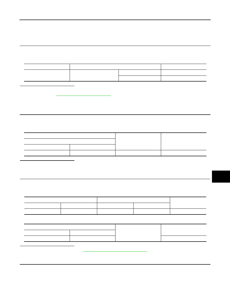
Monitor item

Condition

Status

REQ SW-BD/TR

Back door request switch

Pressed

On

Released

Off

(+)

(–)

Voltage

Back door opener switch assembly

Connector

Terminal 

D94

2

Ground

9 - 16 V

BCM

Back door opener switch assembly

Continuity 

Connector

Terminal

Connector

Terminal

B4

6

D94

2

Existed

BCM

Ground

Continuity 

Connector

Terminal

B4

6

Not existed

DLK-82

< DTC/CIRCUIT DIAGNOSIS >

[TYPE 1]

BACK DOOR REQUEST SWITCH

Is the inspection result normal?

YES

>> GO TO 4.

NO

>> Repair or replace harness.

4.

CHECK BACK DOOR REQUEST SWITCH

Refer to 

DLK-82, "Component Inspection"

.

Is the inspection result normal?

YES

>> GO TO 5.

NO

>> Replace back door opener switch assembly.

5.

CHECK INTERMITTENT INCIDENT

Refer to 

GI-44, "Intermittent Incident"

.

>> INSPECTION END

Component Inspection

INFOID:0000000010479678

1.

CHECK BACK DOOR REQUEST SWITCH

1.

Turn ignition switch OFF.

2.

Disconnect back door opener switch assembly connector.

3.

Check continuity between back door opener switch assembly terminals.

Is the inspection result normal?

YES

>> INSPECTION END

NO

>> Replace back door opener switch assembly.

Back door opener switch assembly

Ground

Continuity 

Connector

Terminal

D94

3

Existed

 Back door opener switch assembly

Condition

Continuity 

Terminal

2

3

Back door request switch

Pressed

Existed

Released

Not existed

COMBINATION METER BUZZER

DLK-83

< DTC/CIRCUIT DIAGNOSIS >

[TYPE 1]

C

D

E

F

G

H

I

J

L

M

A

B

DLK

N

O

P

COMBINATION METER BUZZER

Component Function Check

INFOID:0000000010434580

1.

CHECK FUNCTION

1.

Select “INTELLIGENT KEY” of “BCM” using CONSULT.

2.

Select “INSIDE BUZZER” in “ACTIVE TEST” mode.

3.

Touch “Buzzer 1”, “Buzzer 2” or “Buzzer 3” to check that it works normally.

Is the inspection result normal?

Yes

>> Buzzer (combination meter) is OK.

No

>> Refer to 

DLK-83, "Diagnosis Procedure"

.

Diagnosis Procedure

INFOID:0000000010434581

1.

CHECK METER BUZZER CIRCUIT

Refer to 

WCS-44, "Component Function Check"

.

Is the inspection result normal?

Yes

>> GO TO 2.

No

>> Repair or replace the malfunctioning parts.

2.

CHECK INTERMITTENT INCIDENT

Refer to 

GI-44, "Intermittent Incident"

.

>> INSPECTION END

D L K -8 4

< DTC/CIRCUIT DIAGNOSIS >

[TYPE 1]

DOOR LOCK ACTUATOR

DOOR LOCK ACTUATOR

DRIVER SIDE

DRIVER SIDE : Component Function Check

INFOID:0000000010434582

1.

CHECK FUNCTION

1.

Select “DOOR LOCK” of “BCM” using CONSULT.

2.

Select “DOOR LOCK” in “ACTIVE TEST” mode.

3.

Check that the function operates normally according to the following conditions.

Is the inspection result normal?

YES

>> Door lock actuator is OK.

NO

>> Refer to 

DLK-84, "DRIVER SIDE : Diagnosis Procedure"

.

DRIVER SIDE : Diagnosis Procedure

INFOID:0000000010434583

1.

CHECK DOOR LOCK ACTUATOR INPUT SIGNAL

1.

Turn ignition switch OFF.

2.

Disconnect front door lock assembly (driver side) connector.

3.

Check voltage between front door lock assembly (driver side) harness connector and ground.

Is the inspection result normal?

YES

>> Replace front door lock assembly (driver side).

NO

>> GO TO 2.

2.

CHECK DOOR LOCK ACTUATOR CIRCUIT

1.

Disconnect BCM connector and all door lock assembly connector.

2.

Check continuity between BCM harness connector and front door lock assembly (driver side) harness
connector. 

3.

Check continuity between BCM harness connector and ground.

Is the inspection result normal?

YES

>> GO TO 3.

NO

>> Repair or replace harness.

Monitor item

Status

DOOR LOCK

ALL LOCK

Door lock actuators

LOCK

ALL UNLOCK

UNLOCK

(+)

(–)

Condition

Voltage

Front door lock assembly

(driver side)

Connector

Terminal

D26

2

Ground

Door lock and unlock switch

Unlock

9 – 16 V

3

Lock

BCM

Front door lock assembly (driver side)

Continuity 

Connector

Terminal

Connector

Terminal

M68

141

D26

3

Existed

148

2

BCM

Ground

Continuity 

Connector

Terminal

M68

141

Not existed

148


Content   ..  1201  1202  1203  1204   ..