Content .. 1052 1053 1054 1055 ..
Nissan Qashqai J11. Manual - part 1054
HA-42
< REMOVAL AND INSTALLATION >
[TYPE 1]
A/C UNIT ASSEMBLY
Heater unit
A/C UNIT ASSEMBLY
A/C UNIT ASSEMBLY : Removal and Installation
INFOID:0000000010451996
CAUTION:
Perform lubricant return operation before each refrigeration system disassembly. However, if a large
amount of refrigerant or lubricant is detected, never perform lubricant return operation. Refer to
23, "Perform Lubricant Return Operation"
REMOVAL
1.
Use a refrigerant collecting equipment (for HFO-1234yf) to discharge the refrigerant. Refer to
. (If equipped)
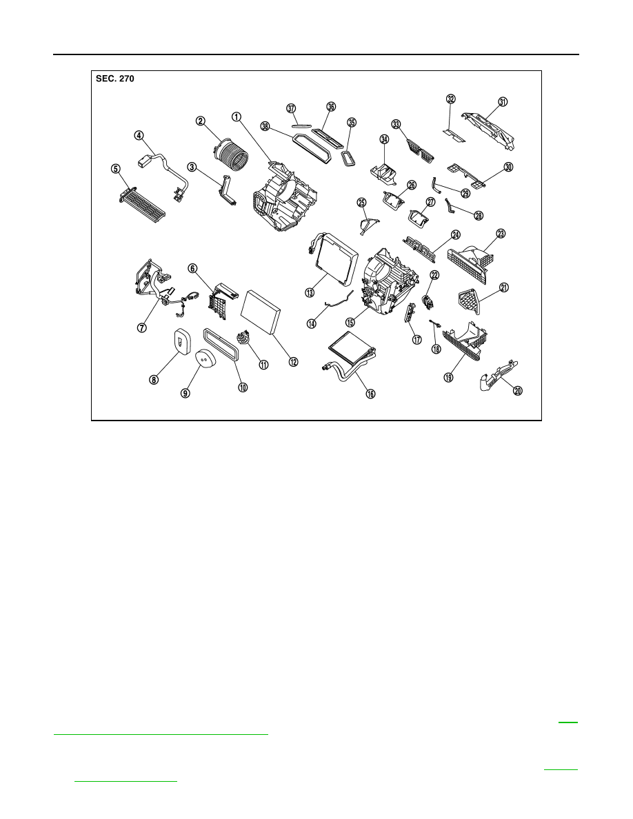
JMIIA3522ZZ
1.
Heater & cooling unit case RH
2.
Blower motor assembly
3.
Filter cover RH
4.
Sub harness
5.
PTC heater
6.
Main case center
7.
Sub harness
8.
Cooler packing
9.
Heater pipe packing
10. Intake packing
11.
Heater pipe clamp
12. Air conditioner filter
13. Evaporator assembly
14.
Case packing
15. Heater & cooling unit case LH
16. Heater core
17.
Filter cover LH
18. Intake sensor
19. Intake box case lower
20.
Heater pipe cover
21. Intake door
22. Power transistor
23.
Intake box case upper
24. Foot door
25. Plate case center
26.
Air mix door RH
27. Air mix door LH
28. Center ventilator door·center venti-
lator & defroster door rod
29.
Foot door & mode door rod
30. Side ventilator door
31. Main case rear
32.
Mode door
33. Center ventilator & defroster door
34. Air guide case
35.
Side ventilator packing LH
36. Center ventilator packing
37. Side ventilator packing RH
38.
Defroster packing