Nissan Qashqai J11. Manual - part 99


  Index      Nissan     Nissan Qashqai J11 - Service and Repair Manual


Search            


Content   ..  97  98  99  100   ..


Nissan Qashqai J11. Manual - part 99


CYLINDER BLOCK

EM-335

< UNIT DISASSEMBLY AND ASSEMBLY >

[K9K]

C

D

E

F

G

H

I

J

K

L

M

A

EM

N

P

O

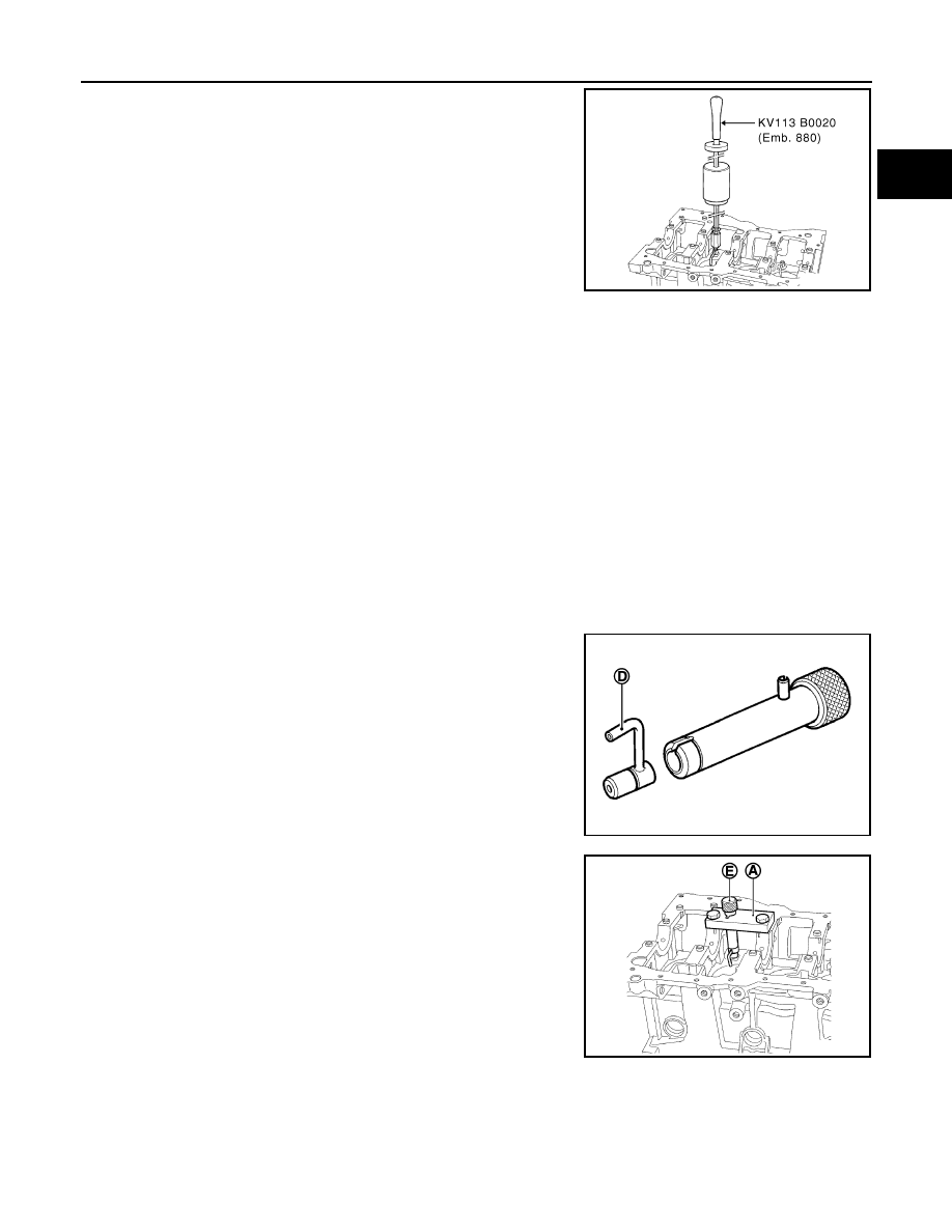
19. Screw sliding hammer [SST: KV113B0020 (Emb. 880)] onto oil

jet remover [SST: KV113B0120 (Mot. 1485-01)] and remove the
oil jet.

20. To remove the piston pin, remove the snap ring using a screwdriver, then release the pin.

Removing the Piston Pins

NOTE:
It is imperative to mark the connecting rod to match it to its piston, because the piston height classes
in the same engine may be different (see Technical Specifications section).

ASSEMBLY

1.

The oil jets must be installed using oil jet remover plate [SST: KV113B0170 (Mot. 1494)].

2.

Install oil jets for NO. 1 and NO. 3 cylinders with the following procedure.

a.

Install plate (A) of oil jet remover plate [SST: KV113B0170 (Mot. 1494)] onto the cylinder block (as shown
in the figure) without tightening the two bolts (C).

b.

Position the guide rod (B) in the plate (A) and the end of the guide rod in the hole of the oil jet to center the
plate (A).

c.

Tighten the two bolts (C).

d.

Remove the guide rod.

e.

Install the push rod instead of the guide rod, then insert the oil jet
into the push rod.
NOTE:
Check that the oil jet is correctly oriented with the end of
the jet (D) directed towards the center of the cylinder.

f.

With a hammer, tap the push rod until the shoulder (E) of the
push rod comes into contact with the plate (A).

3.

Install oil jets for NO. 1 and NO.4 cylinders with the following procedure.

MBIB0451E

MBIB0453E

MBIB0454E

EM-336

< UNIT DISASSEMBLY AND ASSEMBLY >

[K9K]

CYLINDER BLOCK

a.

Fit plate (A) of oil jet remover plate [SST: KV113B0170 (Mot.
1494)] onto the cylinder block (as shown in the figure) without
tightening the two bolts (C).

b.

Position the guide rod (B) in the plate (A) and the end of the guide rod in the hole of the oil jet to center the
plate (A).

c.

Tighten the two bolts (C).

d.

Remove the guide rod.

e.

Position the push rod instead of the guide rod, then insert the oil
jet into the push rod.
NOTE:
Check that the oil jet is correctly oriented with the end of
the jet (D) directed towards the center of the cylinder.

f.

With a hammer, tap the push rod until the shoulder (E) of the
push rod comes into contact with the plate (A).

4.

Check orientation of the oil jets (see diagram below).

5.

Clean the cylinder block and crankshaft by passing a wire
through the lubrication channels.

6.

Install oil level gauge guide tube.

7.

Select main bearing with the following procedure.

a.

Identify the category of crankshaft main journal diameter (A) with checking the marking of crankshaft as
shown in the figure.
NOTE:

MBIB0455E

MBIB0453E

MBIB0456E

A

Orientation of the oil jets of No. 2 and No. 4 cylinders

B

Orientation of the oil jets of No. 1 and No. 3 cylinders

MBIB0457E

CYLINDER BLOCK

EM-337

< UNIT DISASSEMBLY AND ASSEMBLY >

[K9K]

C

D

E

F

G

H

I

J

K

L

M

A

EM

N

P

O

The marking has 5 digits. Left end is the diameter category of
No. 1 bearing (flywheel side) and right end is the diameter cate-
gory of No. 5 bearing (Sprocket side).

Detail of the marking (A):
(1) Line indicating the diameter category of the journal.
(2) Diameter category of the journal No. 1, flywheel end.
(3) Diameter category of the journal No. 5, timing end.
(4) Line indicating the diameter category of crankpin.
(5) Diameter category of crankpin No. 1, flywheel end.
(6) Diameter category crankpin No. 5, timing end

Table Of Journal Diameter Classes

MBIB0344E

E1BIA0409ZZ

E1BIA0408ZZ

Journal diameter category mark

Journal diameter category

[Diameter mm (in)]

A, G, K, R, W

D1

[47.990 - 47.997 (1.8894 - 1.8896)]

B, H, L, S, Y

D2

[47.997 - 48.003 (1.8896 - 1.8899)]

C, J, O, T, Z

D3

[48.003 - 48.010 (1.8899 - 1.8902)]

EM-338

< UNIT DISASSEMBLY AND ASSEMBLY >

[K9K]

CYLINDER BLOCK

b.

Identify the category of main bearing journal inner diameter on
the cylinder block (A) with measuring the length between cylin-
der block top surface and drilled hole (B).

NOTE:
X gives the diameter class of bearing 1 or blue, or, 2 or red.

c.

Select main bearing category by referring to the table.

8.

Install main bearing with the following procedure.

MBIB0345E

E1BIA0717ZZ

Position of (B)

Category marking

[Inner diameter (A) mm (in)]

X = 33 mm (1.30 in)

1 or Blue

[51.936 - 51.942 (2.0447 - 2.0450)]

X = 43 mm (1.69 in)

2 or Red

[51.942 - 51.949 (2.0450 - 2.0452)]

Category of main bearing journal inner di-

ameter on the cylinder block

Category of crankshaft main journal diame-

ter

Main bearing category

[Thickness mm (in)]

1 or Blue

D1

C1 (Yellow)

[1.949 - 1.955 (0.0767 - 0.0770)]

D2

C2 (Blue)

[1.946 - 1.952 (0.0766 - 0.0769)]

D3

C3 (Black)

[1.943 - 1.949 (0.0765 - 0.0767)]

2 or Red

D1

C4 (Red)

[1.953 - 1.959 (0.0769 - 0.0771)]

D2

C1 (Yellow)

[1.949 - 1.955 (0.0767 - 0.0770)]

D3

C2 (Blue)

[1.946 - 1.952 (0.0766 - 0.0769)]


Content   ..  97  98  99  100   ..