Nissan Qashqai J11. Manual - part 71


  Index      Nissan     Nissan Qashqai J11 - Service and Repair Manual


Search            


Content   ..  69  70  71  72   ..


Nissan Qashqai J11. Manual - part 71


CYLINDER BLOCK

EM-223

< UNIT DISASSEMBLY AND ASSEMBLY >

[MR20DD]

C

D

E

F

G

H

I

J

K

L

M

A

EM

N

P

O

Disassembly and Assembly

INFOID:0000000010715516

DISASSEMBLY

1.

Remove oil pan (upper). Refer to 

EM-218, "Exploded View"

.

2.

Remove thermostat housing. Refer to 

CO-51, "Exploded View"

.

3.

Remove knock sensor.

CAUTION:

Handle it carefully and avoid impacts.

4.

Remove crankshaft position sensor (POS) cover and crankshaft position sensor (POS).

CAUTION:

• Handle crankshaft position sensor (POS) carefully and avoid impacts.
• Never disassemble.
• Never place crankshaft position sensor (POS) in a location where it is exposed to magnetism.

5.

Remove oil filter (for intake valve timing control).

6.

Remove piston and connecting rod assembly with the following procedure:
• Before removing piston and connecting rod assembly, check the connecting rod side clearance. Refer to

EM-102, "Inspection"

.

a.

Position crankshaft pin corresponding to connecting rod to be removed onto the bottom dead center. 

b.

Remove connecting rod cap. 
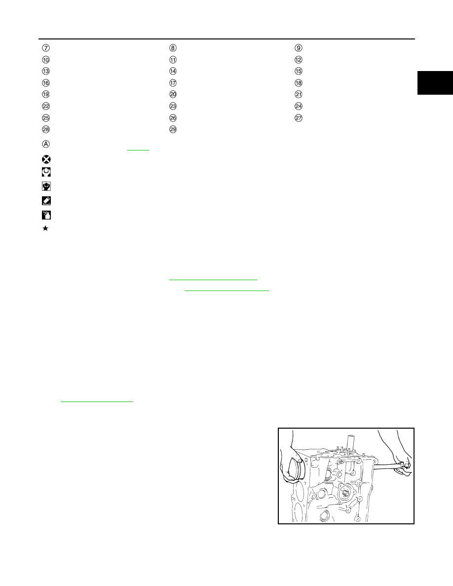
c.

Using a hammer handle or similar tool, push piston and connect-
ing rod assembly out to the cylinder head side. 

CAUTION:

• Be careful not to damage matching surface with connect-

ing rod cap.

• Be careful not to damage the cylinder wall and crankshaft

pin, resulting from an interference of the connecting rod
big end.

7.

Remove connecting rod bearings. 

CAUTION:

When removing them, note the installation position. Keep them in the correct.

Oil pressure switch

Oil tempareture sensor

Oil jet

Top ring

Second ring

Oil ring

Snap ring

Piston

Piston pin

Connecting rod

Thrust bearing

Connecting rod bearing (upper)

Main bearing (upper)

Crankshaft key

Main bearing (lower)

Connecting rod bearing (lower)

Connecting rod cap

Connecting rod cap bolt

Main bearing cap

Main bearing cap bolt

Crankshaft

Signal plate

Rear oil seal

Comply with the installation procedure 
when tightening. Refer to 

EM-223

: Always replace after every disassembly.

: N·m (kg-m, ft-lb)

: N·m (kg-m, in-lb)

: Sealing point

: Should be lubricated with oil.

: Select with proper thickness.

PBIC0259E

EM-224

< UNIT DISASSEMBLY AND ASSEMBLY >

[MR20DD]

CYLINDER BLOCK

8.

Remove piston rings form piston. 
• Before removing piston rings, check the piston ring side clearance. Refer to 

EM-102, "Inspection"

.

• Use a piston ring expander (commercial service tool) (A).

CAUTION:

• When removing piston rings, be careful not to damage

the piston.

• Be careful not to damage piston rings by expanding

them excessively.

9.

Remove piston from connecting rod with the following procedure: 

a.

Using snap ring pliers (A), remove snap rings.

b.

Heat piston to 60 to 70

°

C (140 to 158

°

F) with an industrial use

drier (A) or equivalent.

c.

Push out piston pin with stick (A) of outer diameter approxi-
mately 18 mm (0.71 in).

10. Remove main bearing cap bolts.

• Measure crankshaft end play before loosening main bearing cap bolts. Refer to 

EM-231, "Inspection"

.

JSBIA2493ZZ

JSBIA2494ZZ

JSBIA2495ZZ

JSBIA2496ZZ

CYLINDER BLOCK

EM-225

< UNIT DISASSEMBLY AND ASSEMBLY >

[MR20DD]

C

D

E

F

G

H

I

J

K

L

M

A

EM

N

P

O

• Loosen and remove main bearing cap bolts in the order from

10 to 1 as shown in the figure.

• Use TORX socket.

11. Remove main bearing caps.

• Tap main bearing caps lightly with a plastic hammer for removal. 

CAUTION:

Be careful not to damage the mounting surface.

12. Remove crankshaft.

CAUTION:

• Be careful not to damage or deform signal plate 

mounted on rear end of crankshaft 

.

• When setting crankshaft on a flat floor surface, use a

block of wood to avoid interference between signal plate
and the floor surface.

• Never remove signal plate unless it is necessary to do so.
NOTE:
When removing or installing signal plate, use TORX socket.

13. Pull rear oil seal out from rear end of crankshaft.
14. Remove main bearings and thrust bearings from cylinder block and main bearing caps.

CAUTION:

Identify installation positions, and store them without mixing them up.

ASSEMBLY

CAUTION:

Do not reuse O-rings or washers.
1.

Fully air-blow engine coolant and engine oil passages in cylinder block, cylinder bore and crankcase to
remove any foreign material.

CAUTION:

Use a goggles to protect your eye.

2.

Install each plug to cylinder block as shown in the figure.

CAUTION:

Do not reuse washer.
• Apply liquid gasket to the thread of water drain plug 

.

Use Genuine Liquid Gasket (Three Bond 1215) or equiva-
lent.

• Apply sealant to the thread of plug 

.

Use genuine high strength thread locking sealant (Three
Bond 1386B) or equivalent.
NOTE:
Do not apply liquid gasket or high strength thread locking sealant to the plug 

.

• Tighten each plug as specified below.

: Engine front

JSBIA4604ZZ

PBIC3234J

: Washer

: Engine front

PBIC3999E

EM-226

< UNIT DISASSEMBLY AND ASSEMBLY >

[MR20DD]

CYLINDER BLOCK

3.

Install main bearings and thrust bearings with the following procedure:

a.

Remove dust, dirt, and engine oil on the bearing mating surfaces of cylinder block and main bearing cap.

b.

Install thrust bearings to the both sides of the No. 3 journal hous-
ing 

 on cylinder block.

• Install thrust bearings with the oil groove 

 facing crankshaft

arm (outside). 

c.

Install the main bearings paying attention to the direction.
• Before installing main bearings, apply new engine oil to the bearing surface (inside). Do not apply new

engine oil to the back surface, but thoroughly clean it.

• When installing, align main bearing to the center position of cylinder block and main bearing cap.
• The difference 

 between main bearing (upper) 

 and main

bearing (lower) 

 should be 0.85 mm (0.0335 in) or less when

installing.

• Ensure the oil holes on cylinder block and oil holes 

 on the

main bearings 

 are aligned.

4.

Install signal plate to crankshaft if removed.

a.

Set the signal plate with the flange facing toward the counter weight side (engine front side) to the crank-
shaft rear surface.

b.

Apply new engine oil to threads and seat surfaces of mounting bolts.

Part

Washer

Tightening torque

Yes

54.0 N·m (5.5 kg-m, 40 ft-lb)

No

19.6 N·m (2.0 kg-m, 14 ft-lb)

No

9.8 N·m (1.0 kg-m, 87 in-lb)

: Engine front

PBIC3258J

: Cylinder block

: Main bearing cap

PBIC3237J

PBIC3236J


Content   ..  69  70  71  72   ..