Nissan Qashqai J11. Manual - part 53


  Index      Nissan     Nissan Qashqai J11 - Service and Repair Manual


Search            


Content   ..  51  52  53  54   ..


Nissan Qashqai J11. Manual - part 53


INTAKE MANIFOLD

EM-151

< REMOVAL AND INSTALLATION >

[MR20DD]

C

D

E

F

G

H

I

J

K

L

M

A

EM

N

P

O

e.

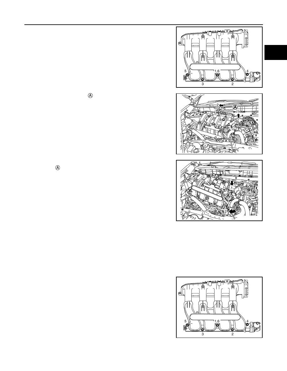
Loosen mounting bolts in the order from 5 to 1 shown in the fig-
ure.

CAUTION:

Cover engine openings to avoid entry of foreign materials.

f.

Lift the surge tank side 

 of intake manifold to move it in the

direction of engine front.
NOTE:
Keep off the brake reservoir tank and A/C low pressure pipe.

g.

Lower the surge tank side to pull out intake manifold runner con-
trol valve 

 from between harness and cylinder head.

8.

Remove brackets from intake manifold, if necessary. (For air duct assembly and/or engine cover)

9.

Remove EVAP canister purge volume control solenoid valve from intake manifold, if necessary.

INSTALLATION

Note the following, and install in the reverse order of removal.

Intake Manifold

1.

Check if gasket is not dropped from the installation groove of intake manifold.

2.

Install intake manifold with the following procedure:

a.

Temporary tighten in the order 4 to 5 as shown in the figure.

b.

Tighten in the order from 1 to 6 as shown in the figure.

JPBIA6813ZZ

JPBIA6833ZZ

JPBIA6834ZZ

JPBIA6813ZZ

EM-152

< REMOVAL AND INSTALLATION >

[MR20DD]

INTAKE MANIFOLD

c.

Tighten intake manifold mounting bolt 

. Then tighten intake

manifold mounting bolt 

.

Electric Throttle Control Actuator

• Tighten bolts of electric throttle control actuator equally and diagonally in several steps.
• Perform “Throttle Valve Closed Position Learning” after repair when removing harness connector of the elec-

tric throttle control actuator. Refer to 

ECM-128, "Description"

.

• Perform “Throttle Valve Closed Position Learning” and “Idle Air Volume Learning” after repair when replacing

electric throttle control actuator. Refer to 

ECM-128, "Description"

 and 

ECM-129, "Description"

.

: Intake manifold

: Engine front

JPBIA6812ZZ

EXHAUST MANIFOLD

EM-153

< REMOVAL AND INSTALLATION >

[MR20DD]

C

D

E

F

G

H

I

J

K

L

M

A

EM

N

P

O

EXHAUST MANIFOLD

Exploded View

INFOID:0000000010715475

Removal and Installation

INFOID:0000000010715476

REMOVAL

1.

Remove intake manifold. Refer to 

EM-149, "Exploded View"

.

2.

Remove the air fuel ratio sensor 1.
• Using heated oxygen sensor wrench [SST: KV10117100], remove air fuel ratio sensor 1.

CAUTION:

Handle air fuel ratio sensor 1 carefully and avoid impacts.

3.

Remove exhaust manifold cover.

4.

Remove exhaust front tube. Refer to 

EX-11, "Exploded View"

.

Exhaust manifold cover

Air fuel ratio sensor 1

Exhaust manifold

Exhaust manifold stay

Gasket

: Always replace after every disassembly.

: N·m (kg-m, ft-lb)

: N·m (kg-m, in-lb)

JPBIA6814GB

EM-154

< REMOVAL AND INSTALLATION >

[MR20DD]

EXHAUST MANIFOLD

5.

Remove exhaust manifold stay 

.

6.

Remove exhaust manifold. 
• Loosen nuts in the order from 5 to 1 as shown in the figure.

NOTE:
Disregard No. 6 to 8 when loosening.

7.

Remove gasket.

CAUTION:

Cover engine openings to avoid entry of foreign materials.

8.

Remove stud bolts from cylinder head.

INSTALLATION

CAUTION:

Never reuse stud bolts, mounting nuts, and gasket. Always replace them with new ones.

1.

Install stud bolts to cylinder head.

2.

Install gasket to cylinder head as shown in the figure.

3.

Install exhaust manifold with the following procedure: 

: Exhaust manifold

: Upper mark

JPBIA6835ZZ

: Engine front

JPBIA6799ZZ

Torx

: Size E8

Torx

: Size E8

: Identification

: Engine front

JPBIA5141ZZ


Content   ..  51  52  53  54   ..