Nissan Qashqai J11. Manual - part 32


  Index      Nissan     Nissan Qashqai J11 - Service and Repair Manual


Search            


Content   ..  30  31  32  33   ..


Nissan Qashqai J11. Manual - part 32


TIMING CHAIN

EM-67

< UNIT DISASSEMBLY AND ASSEMBLY >

[HRA2DDT]

C

D

E

F

G

H

I

J

K

L

M

A

EM

N

P

O

e.

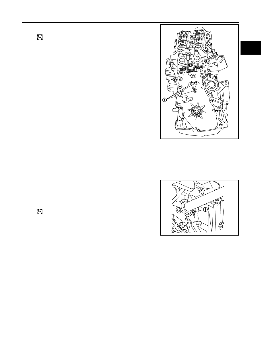
After all bolts are tightened, instal front cover bolts (1).

9.

Insert crankshaft pulley by aligning with crankshaft key. 
• When inserting crankshaft pulley with a plastic hammer, tap on its center portion (not circumference).

CAUTION:

Install protecting front oil seal lip section from any damage.

10. Tighten crankshaft pulley bolt with the following procedure:

• Lock the flywheel (1) using a flat blade screw driver.

a.

Apply new engine oil to thread and seat surfaces of crankshaft
pulley bolt.

b.

Tighten crankshaft pulley bolt.

c.

Turn another 200 degrees clockwise (angle tightening).
• Check the tightening angle with movement of one angle mark.

11. Check that crankshaft turns smoothly by rotating by hand clockwise.
12. Install in the reverse order of removal.

Inspection

INFOID:0000000010351306

INSPECTION AFTER REMOVAL

Timing Chain

: 10.0 N·m (1.0 kg-m, 7 ft-lb)

E1BIA1089ZZ

: 50.0 N·m (5.1 kg-m, 37 ft-lb)

E1BIA1090ZZ

EM-68

< UNIT DISASSEMBLY AND ASSEMBLY >

[HRA2DDT]

TIMING CHAIN

Check for cracks (A) and any excessive wear (B) at link plates and
roller links of timing chain. Replace timing chain if necessary.

INSPECTION AFTER INSTALLATION

Inspection for Leakage

The following are procedures for checking fluids leakage, lubricates leakage, and exhaust gases leakage.
• Before starting engine, check oil/fluid levels including engine coolant and engine oil. If less than required

quantity, fill to the specified level. Refer to 

MA-59, "Fluids and Lubricants"

.

• Use procedure below to check for fuel leakage.
- Turn ignition switch “ON” (with engine stopped). With fuel pressure applied to fuel piping, check for fuel leak-

age at connection points.

- Start engine. With engine speed increased, check again for fuel leakage at connection points.
• Run engine to check for unusual noise and vibration.

NOTE:
If hydraulic pressure inside chain tensioner drops after removal/installation, slack in guide may generate a
pounding noise during and just after the engine start. However, this does not indicate an unusualness. Noise
will stop after hydraulic pressure rises.

• Warm up engine thoroughly to check there is no leakage of fuel, or any oil/fluids including engine oil and

engine coolant.

• Bleed air from lines and hoses of applicable lines, such as in cooling system.
• After cooling down engine, again check oil/fluid levels including engine oil and engine coolant. Refill to the

specified level, if necessary.

Summary of the inspection items:

*: Power steering fluid, brake fluid, etc.

PBIC3169J

Items

Before starting engine

Engine running

After engine stopped

Engine coolant

Level

Leakage

Level

Engine oil

Level

Leakage

Level

Transmission / 
transaxle fluid

AT & CVT Models

Leakage

Level / Leakage

Leakage

MT Models

Level / Leakage

Leakage

Level / Leakage

Other oils and fluids*

Level

Leakage

Level

Fuel

Leakage

Leakage

Leakage

Exhaust gases

Leakage

CYLINDER HEAD

EM-69

< UNIT DISASSEMBLY AND ASSEMBLY >

[HRA2DDT]

C

D

E

F

G

H

I

J

K

L

M

A

EM

N

P

O

CYLINDER HEAD

Exploded View

INFOID:0000000010282237

REMOVAL

Refer to 

GI-4, "Components"

 for symbols in the figure.

DISASSEMBLY

1.

Cylinder head bolt

2.

Cylinder head bolt washer

3.

Cylinder head

4.

Cylinder head gasket

5.

Dowel pin

6.

Cylinder block

A.

Tightening must be done following the installation procedure.
Refer to 

EM-70

E1BIA1018GB

EM-70

< UNIT DISASSEMBLY AND ASSEMBLY >

[HRA2DDT]

CYLINDER HEAD

Refer to 

GI-4, "Components"

 for symbols in the figure.

Removal and Installation

INFOID:0000000010282238

REMOVAL

1.

Release fuel pressure. Refer to 

ECH-121, "Work Procedure"

.

2.

Drain engine coolant and engine oil. Refer to 

CO-11, "Draining"

 and 

LU-9, "Draining"

.

CAUTION:

Perform this step when the engine is cold.

3.

Remove the following components and related parts.
• Intake manifold: Refer to 

EM-25, "Exploded View"

.

• Fuel tube and fuel injector: Refer to 

EM-42, "Exploded View"

.

• High pressure fuel pump: Refer to 

EM-38, "Exploded View"

• Water outlet: Refer to 

CO-27, "Exploded View"

.

• Exhaust manifold: Refer to 

EM-37, "Exploded View"

.

• Rocker cover: Refer to 

EM-49, "Exploded View"

.

• Front cover and timing chain: Refer to 

EM-93, "Exploded View"

.

• Camshaft: Refer to 

EM-77, "Exploded View"

.

1.

Intake valve lifter

2.

Intake valve collet

3.

Intake valve spring retainer

4.

Intake valve spring

5.

Intake valve oil seal 

6.

Intake valve guide

7.

Intake valve seat

8.

Intake valve

9.

Cylinder head

10. Intake camshaft

11. Exhaust camshaft

12. Exhaust valve

13. Exhaust valve seat

14. Exhaust valve guide

15. Exhaust valve oil seal 

16. Exhaust valve spring

17. Exhaust valve spring retainer

18. Exhaust valve collet

19. Exhaust valve lifter

A.

Replacement must be following the disassembly and assembly procedure.
 Refer to 

EM-71

E1BIA1019GB


Content   ..  30  31  32  33   ..