Nissan Juke (2016 year). Service Repair Manual - part 3
AV-12
< SYSTEM DESCRIPTION >
[DISPLAY AUDIO]
SYSTEM
• Spoken voice sound output from the microphone (microphone signal) is input to audio unit.
• Audio unit outputs to cellular phone with Bluetooth
®
communication as a TEL voice signal.
• Voice sound is then heard at the other party.
When Receiving A Call
• Voice sound is input to own cellular phone from the other party.
• TEL voice signal is input to audio unit by establishing Bluetooth
®
communication from cellular phone, and
the signal is output to front speakers.
SPEED SENSITIVE VOLUME SYSTEM
Volume level of this system goes up and down automatically in proportion to the vehicle speed. The control
level can be selected by the customer. Refer to Owner's Manual for operating instructions.
REAR VIEW MONITOR FUNCTION
Operation Description
• When the selector lever is shifted to the reverse position, the rear view monitor image is displayed.
• When the selector lever is shifted to any position other than the reverse position, the original image (the
image displayed before the rear view monitor image) is displayed.
Camera Image Operation Principle
• The audio unit supplies power to the rear view camera when receiving a reverse signal.
• The rear view camera transmits camera images to the audio unit when power is supplied from the audio unit.
• The audio unit combines a warning message and fixed guide lines with an image received from the rear view
camera to display a rear view camera image on the screen.
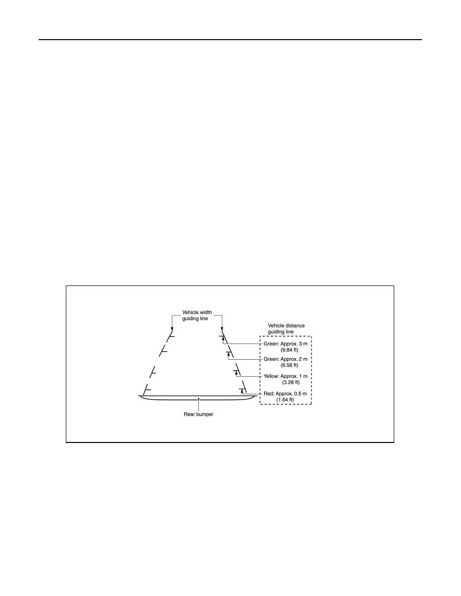
Vehicle Width and Distance Guide Lines Display Function at Rear View Monitor Display
• The vehicle width and distance guide lines are displayed at the rear view monitor display to allow the driver
to more easily judge distances between the vehicle and objects and help the driver back into a parking
space.
Vehicle Width and Distance Guide Lines Display Function at Rear View Monitor Display
Precautions for Vehicle Width And Distance Guide Lines Display on the Rear View Monitor Display
Vehicle width and distance guide lines on the display may be different from actual lines depending on vehicle
conditions and road conditions.
Precautions for road conditions
JSNIA4330GB
Revision: November 2015
2016 JUKE