Nissan Juke F15. Manual - part 946
LAN
CAN COMMUNICATION CIRCUIT
LAN-121
< DTC/CIRCUIT DIAGNOSIS >
[CAN SYSTEM (TYPE 4)]
C
D
E
F
G
H
I
J
K
L
B
A
O
P
N
CAN COMMUNICATION CIRCUIT
Diagnosis Procedure
INFOID:0000000012200591
1.
CONNECTOR INSPECTION
1. Turn the ignition switch OFF.
2. Disconnect the battery cable from the negative terminal.
3. Disconnect all the unit connectors on CAN communication system.
4. Check terminals and connectors for damage, bend and loose connection.
Is the inspection result normal?
YES
>> GO TO 2.
NO
>> Repair the terminal and connector.
2.
CHECK HARNESS CONTINUITY (SHORT CIRCUIT)
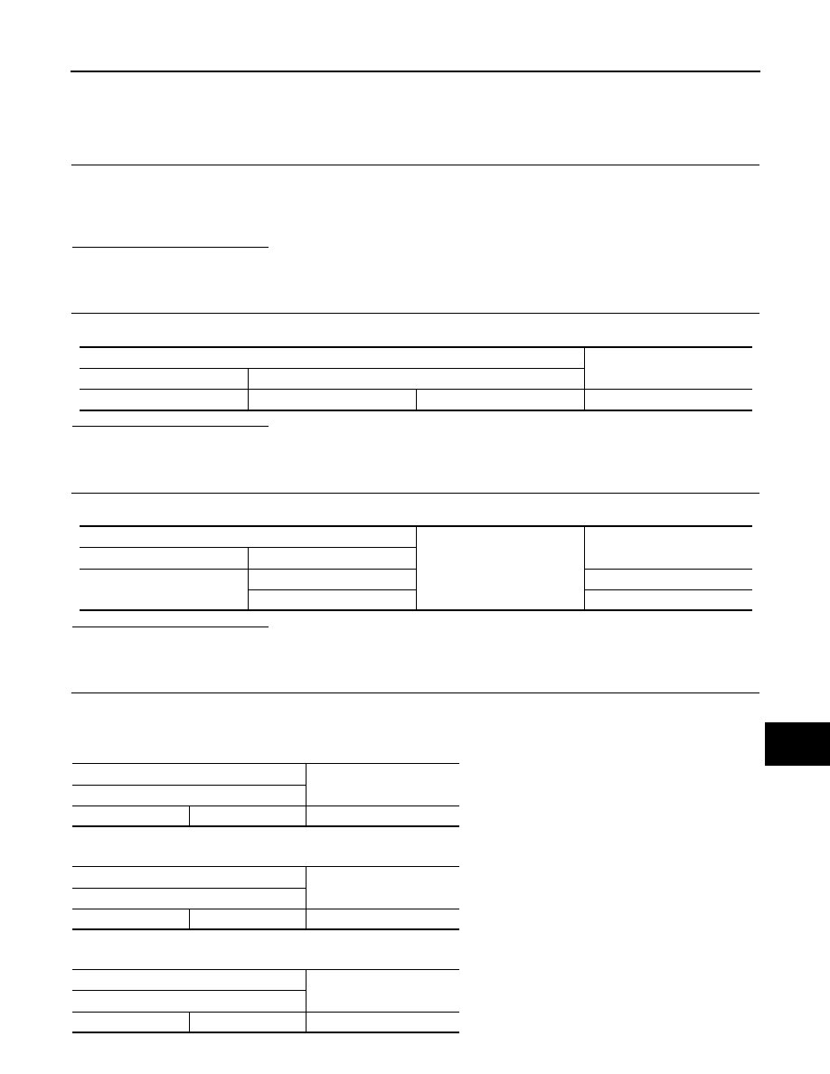
Check the continuity between the data link connector terminals.
Is the inspection result normal?
YES
>> GO TO 3.
NO
>> Check the harness and repair the root cause.
3.
CHECK HARNESS CONTINUITY (SHORT CIRCUIT)
Check the continuity between the data link connector and the ground.
Is the inspection result normal?
YES
>> GO TO 4.
NO
>> Check the harness and repair the root cause.
4.
CHECK ECM AND BCM TERMINATION CIRCUIT
1. Remove the ECM and the BCM.
2. Check the resistance between the ECM terminals.
-
For NISMO RS models
-
Except for NISMO RS models
3. Check the resistance between the BCM terminals.
Data link connector
Continuity
Connector No.
Terminal No.
M4
6
14
Not existed
Data link connector
Ground
Continuity
Connector No.
Terminal No.
M4
6
Not existed
14
Not existed
ECM
Resistance (
Ω)
Terminal No.
100
99
Approx. 108 – 132
ECM
Resistance (
Ω)
Terminal No.
124
123
Approx. 108 – 132
BCM
Resistance (
Ω)
Terminal No.
39
40
Approx. 108 – 132