Nissan Juke F15. Manual - part 919


  Index      Nissan     Nissan Juke F15 (2015 year) - Service and Repair Manual


Search            


Content   ..  917  918  919  920   ..


Nissan Juke F15. Manual - part 919


LAN

TROUBLE DIAGNOSIS

LAN-13

< SYSTEM DESCRIPTION >

[CAN FUNDAMENTAL]

C

D

E

F

G

H

I

J

K

L

B

A

O

P

N

NOTE:

When data link connector branch line is open, transmission and reception of CAN communication signals are

not affected. Therefore, no symptoms occur. However, be sure to repair malfunctioning circuit.

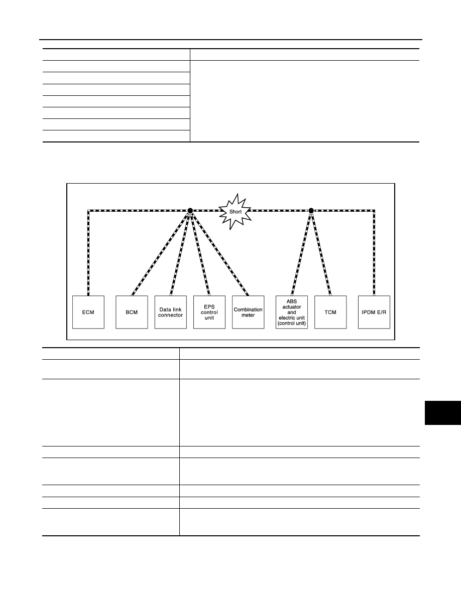
Example: CAN-H, CAN-L Harness Short Circuit

CAN Diagnosis with CONSULT

INFOID:0000000012200495

CAN diagnosis on CONSULT extracts the root cause by receiving the following information.

Unit name

Major symptom

ECM

Normal operation.

BCM

EPS control unit

Combination meter

ABS actuator and electric unit (control unit)

TCM

IPDM E/R

JSMIA0445GB

Unit name

Major symptom

ECM

• Engine torque limiting is affected, and shift harshness increases.
• Engine speed drops.

BCM

• Reverse warning chime does not sound.
• The front wiper moves under continuous operation mode even though the front 

wiper switch being in the intermittent position.

• The room lamp does not turn ON.
• The engine does not start (if an error or malfunction occurs while turning the igni-

tion switch OFF.)

• The steering lock does not release (if an error or malfunction occurs while turning 

the ignition switch OFF.)

EPS control unit

The steering effort increases.

Combination meter

• The tachometer and the speedometer do not move.
• Warning lamps turn ON.
• Indicator lamps do not turn ON.

ABS actuator and electric unit (control unit)

Normal operation.

TCM

No impact on operation.

IPDM E/R

When the ignition switch is ON,
• The headlamps (Lo) turn ON.
• The cooling fan continues to rotate.

LAN-14

< SYSTEM DESCRIPTION >

[CAN FUNDAMENTAL]

TROUBLE DIAGNOSIS

• Response to the system call

• Control unit diagnosis information

• Self-diagnosis

• CAN diagnostic support monitor

Self-Diagnosis

INFOID:0000000012200496

If communication signals cannot be transmitted or received among units communicating via CAN communica-

tion line, CAN communication-related DTC is displayed on the CONSULT “Self Diagnostic Result” screen.

NOTE:

The following table shows examples of CAN communication-related DTC. For other DTC, refer to the applica-

ble sections.

CAN Diagnostic Support Monitor

INFOID:0000000012200497

MONITOR ITEM (CONSULT)

Example: CAN DIAG SUPPORT MNTR indication

Without PAST

DTC

Self-diagnosis item

 (CONSULT indication)

DTC detection condition

Inspection/Action

U1000

CAN COMM CIRCUIT

ECM

When ECM is not transmitting or receiving CAN 
communication signal of OBD (emission-relat-
ed diagnosis) for 2 seconds or more.

Start the inspection. Re-
fer to the applicable sec-
tion of the indicated 
control unit.

Except 
for ECM

When a control unit (except for ECM) is not 
transmitting or receiving CAN communication 
signal for 2 seconds or more.

U1001

CAN COMM CIRCUIT

When ECM is not transmitting or receiving CAN communi-
cation signal other than OBD (emission-related diagnosis) 
for 2 seconds or more.

U1002

SYSTEM COMM

When a control unit is not transmitting or receiving CAN 
communication signal for 2 seconds or less.

U1010

CONTROL UNIT(CAN)

When an error is detected during the initial diagnosis for 
CAN controller of each control unit.

Replace the control unit 
indicating “U1010”.

JSMIA0964GB

Item

PRESENT

Description

Initial diagnosis

OK

Normal at present

NG

Control unit error (Except for some control units)

LAN

TROUBLE DIAGNOSIS

LAN-15

< SYSTEM DESCRIPTION >

[CAN FUNDAMENTAL]

C

D

E

F

G

H

I

J

K

L

B

A

O

P

N

With PAST

Transmission diagnosis

OK

Normal at present

UNKWN

Unable to transmit signals for 2 seconds or more.

Diagnosis not performed

Control unit name

(Reception diagnosis)

OK

Normal at present

UNKWN

Unable to receive signals for 2 seconds or more.

Diagnosis not performed

No control unit for receiving signals. (No applicable optional parts)

Item

PRESENT

Description

Item

PRESENT

PAST

Description

Transmission diagnosis

OK

OK

Normal at present and in the past

1 – 39

Normal at present, but unable to transmit signals for 2 seconds or more 
in the past. (The number indicates the number of ignition switch cycles 
from OFF to ON.)

UNKWN

0

Unable to transmit signals for 2 seconds or more at present.

Control unit name

(Reception diagnosis)

OK

OK

Normal at present and in the past

1 – 39

Normal at present, but unable to receive signals for 2 seconds or more 
in the past. (The number indicates the number of ignition switch cycles 
from OFF to ON.)

UNKWN

0

Unable to receive signals for 2 seconds or more at present.

Not diagnosed

Diagnosis not performed.

No control unit for receiving signals. (No applicable optional parts)

LAN-16

< SYSTEM DESCRIPTION >

[CAN FUNDAMENTAL]

TROUBLE DIAGNOSIS

How to Use CAN Communication Signal Chart

INFOID:0000000012200498

The CAN communication signal chart lists the signals needed for trouble diagnosis. It is useful for detecting

the root cause by finding a signal related to the symptom, and by checking transmission and reception unit.

JSMIA0446GB


Content   ..  917  918  919  920   ..