Nissan Juke F15. Manual - part 888


  Index      Nissan     Nissan Juke F15 (2015 year) - Service and Repair Manual


Search            


Content   ..  886  887  888  889   ..


Nissan Juke F15. Manual - part 888


SYSTEM

INL-7

< SYSTEM DESCRIPTION >

C

D

E

F

G

H

I

J

K

M

A

B

INL

N

O

P

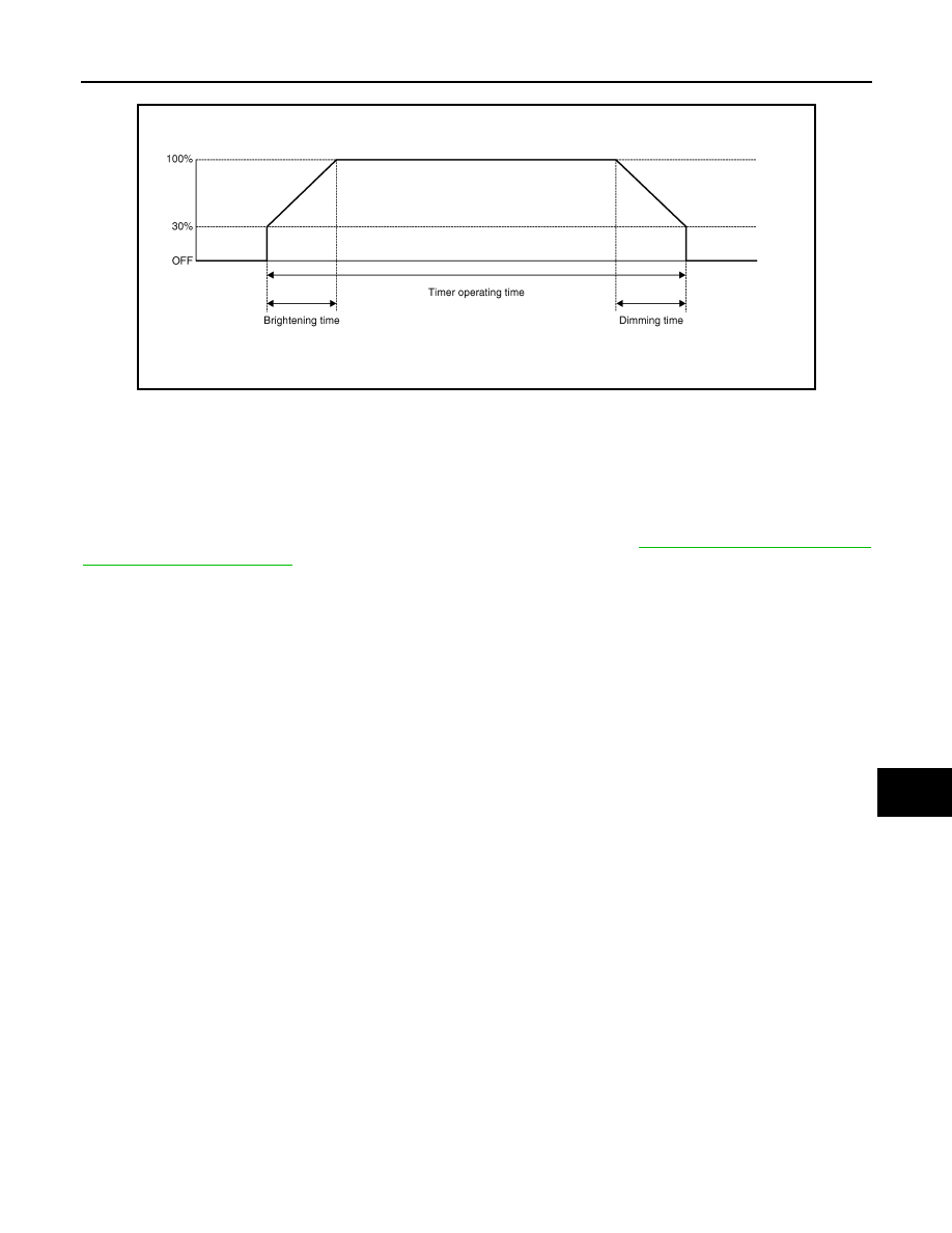
Interior Room Lamp Timer Basic Operation

• The interior room lamp turns ON and OFF (gradual brightening and dimming) by the interior room lamp

timer.

• BCM judges the vehicle condition with the following items. It activates the interior room lamp timer.

- Ignition switch status

- Door switch signal (except back door)

- Door lock/unlock signal (Remote keyless entry receiver, each door request switch, door lock and unlock

switch, key cylinder switch)

NOTE:

Each function of interior room lamp timer can be set by CONSULT. Refer to 

INL-12, "INT LAMP : CONSULT

Function (BCM - INT LAMP)"

.

Interior Room Lamp ON Operation

• BCM always turns the interior room lamp ON when any door opens except back door.

• BCM activates the interior room lamp timer in any of the following conditions to turn the interior room lamp

ON for a period of time.

- Status of all doors except back door changes from open to close

- Ignition switch is turned ON 

→ OFF

- Door unlock signal is detected when all doors close except back door with ignition switch OFF

NOTE:

The timer restarts if new condition is input during the timer operating time.

Interior Room Lamp OFF Operation

BCM stops the timer in any of the following conditions to turn the interior room lamp OFF.

• The timer operating time is expired

• Ignition switch is turned OFF 

→ ACC/ON

• Door lock signal is detected with all doors close except back door.

LUGGAGE ROOM LAMP CONTROL

BCM turns luggage room lamp ON when the following condition is detected.

• Back door switch is ON

BCM turns luggage room lamp OFF when the following condition is detected.

• Back door switch is OFF

PUSH-BUTTON IGNITION SWITCH ILLUMINATION CONTROL

Push-button Ignition Switch Illumination Basic Operation

BCM provides the power supply to turn the push-button ignition switch illumination ON.

Push-button Ignition Switch Illumination ON Operation

BCM turns the push-button ignition switch illumination ON in the following conditions.

• Ignition switch ON

• Tail lamp ON

• Any of the following conditions with ignition switch OFF/ACC

- Engine start permission is entered

- Driver side door is LOCK 

→ UNLOCK

- Driver side door is open

JPLIA0093GB

INL-8

< SYSTEM DESCRIPTION >

SYSTEM

Push-button Ignition Switch Illumination OFF Operation

BCM turns the push-button ignition switch illumination OFF in any of the following conditions.

• The push-button ignition switch illumination ON conditions do not satisfy.

• Any of the following conditions with ignition switch OFF.

- The push-button ignition switch illumination ON conditions do not change (15 seconds after the ignition

switch OFF)

- Driver side door is UNLOCK 

→ LOCK

INTERIOR ROOM LAMP BATTERY SAVER SYSTEM
INTERIOR ROOM LAMP BATTERY SAVER SYSTEM : System Diagram

INFOID:0000000012196999

INTERIOR ROOM LAMP BATTERY SAVER SYSTEM : System Description

INFOID:0000000012197000

OUTLINE

• Interior room lamp battery saver is controlled by BCM.

• BCM turns applicable lamps OFF depending on the vehicle condition. This function prevents the battery

from over-discharging if the driver neglects turning OFF the lamps.

Applicable lamps

• Map lamp

• Luggage room lamp

INTERIOR ROOM LAMP BATTERY SAVER FUNCTION

• When the ignition switch is turned to other position than ON, BCM operates the timer for a period of time to

cut the interior room lamp power supply.

• BCM restarts the timer when any of the following signals changes while operating the timer.

- Ignition switch status

- Door switch signal (ALL)

- Door lock/unlock signal (remote keyless entry receiver, each door request switch, door lock and unlock

switch, key cylinder switch)

JMLIA6151GB

SYSTEM

INL-9

< SYSTEM DESCRIPTION >

C

D

E

F

G

H

I

J

K

M

A

B

INL

N

O

P

• BCM provides the interior room lamp power supply continuously when the ignition switch position is ON.

NOTE:

Each function of interior room lamp battery saver can be set by CONSULT. Refer to 

INL-13, "BATTERY

SAVER : CONSULT Function (BCM - BATTERY SAVER)"

.

ILLUMINATION CONTROL SYSTEM
ILLUMINATION CONTROL SYSTEM : System Diagram

INFOID:0000000012197001

ILLUMINATION CONTROL SYSTEM : System Description

INFOID:0000000012197002

OUTLINE

Each illumination lamp is controlled by each function of BCM and IPDM E/R.

Control by BCM

• Combination switch reading function

• Headlamp control function

Control by IPDM E/R

• Relay control function

Control by combination meter

• Meter illumination control function (Refer to 

MWI-11, "SPEEDOMETER : System Description"

.)

ILLUMINATION CONTROL

• BCM detects the combination switch condition by the combination switch reading function.

• BCM transmits position light request signal to IPDM E/R and combination meter according to tail lamp ON

condition.

Tail lamp ON condition

- Lighting switch 1ST

- Lighting switch 2ND

- Lighting switch AUTO, and the auto light function ON judgment (With auto light system)

• IPDM E/R turns the integrated tail lamp relay ON according to position light request signal. It provides the

power supply to each illumination lamp. 

• Combination meter enters in the nighttime mode according to position light request signal. Under the night-

time mode the combination meter controls the illuminance by controlling the each illumination lamp (ground

side).

JMLIA2724GB

INL-10

< SYSTEM DESCRIPTION >

DIAGNOSIS SYSTEM (BCM)

DIAGNOSIS SYSTEM (BCM)

COMMON ITEM
COMMON ITEM : CONSULT Function (BCM - COMMON ITEM)

INFOID:0000000012946726

APPLICATION ITEM

CONSULT performs the following functions via CAN communication with BCM.

SYSTEM APPLICATION

BCM can perform the following functions for each system.

NOTE:

It can perform the diagnosis modes except the following for all sub system selection items.

×: Applicable item

NOTE:
*: For models with automatic A/C, this diagnosis mode is not used.

FREEZE FRAME DATA (FFD)

The BCM records the following vehicle condition at the time a particular DTC is detected, and displays on

CONSULT.

Diagnosis mode

Function Description

Work Support

Changes the setting for each system function.

Self Diagnostic Result

Displays the diagnosis results judged by BCM.

CAN Diag Support Monitor

Monitors the reception status of CAN communication viewed from BCM.

Data Monitor

The BCM input/output signals are displayed.

Active Test

The signals used to activate each device are forcibly supplied from BCM.

Ecu Identification

The BCM part number is displayed.

Configuration

• Read and save the vehicle specification.
• Write the vehicle specification when replacing BCM.

System

Sub system selection item

Diagnosis mode

Work Support

Data Monitor

Active Test

Door lock

DOOR LOCK

×

×

×

Rear window defogger

REAR DEFOGGER

×

×

Warning chime

BUZZER

×

×

Interior room lamp timer

INT LAMP

×

×

×

Exterior lamp

HEAD LAMP

×

×

×

Wiper and washer

WIPER

×

×

×

Turn signal and hazard warning lamps

FLASHER

×

×

×

Air conditioning system

AIR CONDITONER

×

×*

• Intelligent Key system
• Engine start system

INTELLIGENT KEY

×

×

×

Combination switch

COMB SW

×

Body control system

BCM

×

NVIS - NATS

IMMU

×

×

×

Interior room lamp battery saver

BATTERY SAVER

×

×

×

Back door open

TRUNK

×

Theft warning alarm

THEFT ALM

×

×

×

RAP

RETAINED PWR

×

Signal buffer system

SIGNAL BUFFER

×

×

TPMS

AIR PRESSURE MONITOR

×

×

×


Content   ..  886  887  888  889   ..