Nissan Juke F15. Manual - part 845


  Index      Nissan     Nissan Juke F15 (2015 year) - Service and Repair Manual


Search            


Content   ..  843  844  845  846   ..


Nissan Juke F15. Manual - part 845


SYSTEM

HAC-15

< SYSTEM DESCRIPTION >

[AUTOMATIC AIR CONDITIONING]

C

D

E

F

G

H

J

K

L

M

A

B

HAC

N

O

P

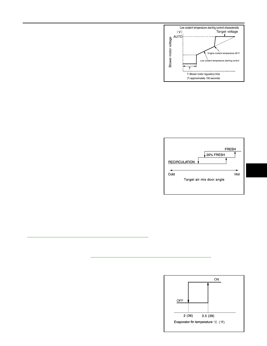
If the engine coolant temperature is 56

°C (133°F) or less, to prevent

a cold discharged air flow, A/C auto amp. suspends blower motor

activation for the maximum 150 seconds depending on target air mix

door opening angle. After this, voltage of blower motor is increased

gradually, and blower motor is activated.

FAN SPEED CONTROL AT DOOR MOTOR OPERATION

When mode door motor is activated while air flow is more than the specified value, A/C auto amp. reduces

temporarily fan speed so that mode door moves smoothly.

HIGH IN- TEMPERATURE STARTING CONTROL

When evaporator temperature is high [intake air temperature sensor value is 35

°C (95°F) or more], to prevent

a hot discharged air flow, A/C auto amp. suspends blower motor activation for approximately 3 seconds so

that evaporator is cooled by refrigerant.

Air Inlet Control

INFOID:0000000012200013

• While air inlet is in automatic control, A/C auto amp. selects air

inlet (fresh air intake, 20% fresh air intake, or recirculation)

depending on set temperature, in-vehicle temperature, and ambi-

ent temperature.

NOTE:

Air inlet is fixed to REC, when the ambient temperature is 21

°C

(70

°F) or more.

• Air inlet is fixed to 80% FRE, only when the conditions are satisfied

as follows:

- Air inlet is FOOT or D/F

- Ambient temperature is 2

°C (36°F) or less

- Maximum fan speed

Compressor Control

INFOID:0000000012200014

DESCRIPTION

• When the compressor activation condition is satisfied while blower motor is activated, A/C auto amp. trans-

mits A/C ON signal and blower fan ON signal to BCM.

• BCM transmits the A/C ON signal and blower fan ON signal to ECM via CAN communication line. Refer to

BCS-12, "SIGNAL BUFFER SYSTEM : System Description"

.

• ECM judges the conditions of each sensor (Refrigerant pressure sensor signal, accelerator position signal,

etc.), and transmits the A/C compressor request signal to IPDM E/R via CAN communication line.

• By receiving the A/C compressor request signal from ECM, IPDM E/R turns the A/C relay to ON, and acti-

vates the compressor. Refer to 

PCS-7, "RELAY CONTROL SYSTEM : System Description"

.

CONTROL BY A/C AUTO AMP.

Low Temperature Protection Control

When intake sensor detects that evaporator fin temperature is 2

°C

(36

°F) or less, A/C auto amp. requests ECM to turn the compressor

OFF, and stops the compressor.

When the air temperature returns to 3.5

°C (38°F) or more, the com-

pressor is activated.

JMIIA1227GB

JMIIA0711GB

JMIIA1055GB

HAC-16

< SYSTEM DESCRIPTION >

[AUTOMATIC AIR CONDITIONING]

SYSTEM

CONTROL BY ECM

Compressor Protection Control at Pressure Malfunction

When the high-pressure side value that is detected by refrigerant pressure sensor is as per the following state,

ECM requests IPDM E/R to turn A/C relay OFF and stops the compressor.
• 3.12 MPa (31.82 kg/cm

2

, 452.4 psi) or more (When the engine speed is less than 1,500 rpm)

• 2.74 MPa (27.95 kg/cm

2

, 397.3 psi) or more (When the engine speed is 1,500 rpm or more)

• 0.14 MPa (1.43 kg/cm

2

, 20.3 psi) or less

Compressor Oil Circulation Control

When the engine starts while the engine coolant temperature is 56

°C (133°F) or less, ECM activates the com-

pressor for approximately 6 seconds and circulates the compressor oil once.

Air Conditioning Cut Control

When the engine condition is high load, ECM transmit A/C relay OFF request to IPDM E/R, and stops the

compressor. Refer to 

EC-63, "AIR CONDITIONING CUT CONTROL : System Description"

.

Door Control

INFOID:0000000012200015

DOOR MOTOR CONTROL

• A/C auto amp. receives the detection data from each sensor. 

• Intake door motor, when receiving control signal from A/C auto amp. moves intake door to the appropriate

position based on the door position detection signal of each PBR (Potentio Balance Resistor).

• Each motor of air mix and mode, when receiving drive signal from A/C auto amp., moves each door to the

appropriate position according to drive signal.

DRIVE METHOD OF STEPPING MOTOR TYPE MOTOR

• Stepping motor type motor is driven by 4 pieces of drive coil that are sequentially excited. 

• Direction of rotation is changeable by recomposing pattern of excitation. 

SWITCH AND THEIR CONTROL FUNCTION

SJIA0971E

SYSTEM

HAC-17

< SYSTEM DESCRIPTION >

[AUTOMATIC AIR CONDITIONING]

C

D

E

F

G

H

J

K

L

M

A

B

HAC

N

O

P

*: Models for Canada

1.

Intake door

2.

Blower motor

3.

In-cabin microfilter filter

4.

Evaporator

5.

Upper air mix door

6.

Lower air mix door

7.

Heater core

8.

Foot door

9.

Side ventilator door

10. Sub defroster door

11. Center ventilator and defroster door

Fresh air intake

Recirculation air

Defroster

Center ventilator

Side ventilator

Foot

Rear foot

*

Switch/dial position

Door position

Ce

nt

er

 ve

nt

ila

to

r an

d d

ef

ros

ter do

or

Su

b d

ef

ros

ter 

do

or

Si

de

 ve

nt

ila

tor do

or

Fo

ot

 do

or

In

ta

ke

 do

or

Up

pe

r ai

r mi

do

or

L

owe

r ai

r mi

do

or

AUTO switch

AUTO

JPIIA1584ZZ

HAC-18

< SYSTEM DESCRIPTION >

[AUTOMATIC AIR CONDITIONING]

SYSTEM

AIR DISTRIBUTION

Models except for Canada

Models for Canada

MODE switch

VENT

P

M

L

G

B/L

N

K

H

FOOT

Q

O

J

I

D/F

N

DEF switch

M

G

Intake switch

A

B

Temperature control dial

Full cold

18

°C (60°F)

D

E

18.5

°C (61°F) – 

31.5

°C (89°F)

AUTO

AUTO

Full hot

32

°C (90°F)

C

F

OFF switch

Q

O

J

I

B

Switch/dial position

Door position

Ce

nte

r v

en

tila

to

r an

de

fros

te

r do

or

Su

b de

fr

os

te

r do

or

Si

de

 v

ent

ila

to

r do

or

Fo

ot

 do

or

In

ta

ke

 do

or

Up

pe

r ai

r mi

x do

or

Lo

we

r ai

r mi

x do

or

Discharge air flow

MODE/DEF setting po-

sition

Air outlet/distribution

Ventilator

Foot

Defroster

Center

Side

52.6%

47.3%

34.0%

27.7%

38.4%

19.1%

57.9%

23.0%

13.5%

42.4%

44.1%

16.3%

83.8%

Discharge air flow

MODE/DEF setting 

position

Air outlet/distribution

Ventilator

Foot

Defroster

Center

Side

Front

Rear

52.6%

47.3%

28.2%

25.9%

29.6%

16.3%

16.3%

43.0%

21.0%

19.7%


Content   ..  843  844  845  846   ..