Nissan Juke F15. Manual - part 833
DIAGNOSIS AND REPAIR WORKFLOW
HA-15
< BASIC INSPECTION >
C
D
E
F
G
H
J
K
L
M
A
B
HA
N
O
P
BASIC INSPECTION
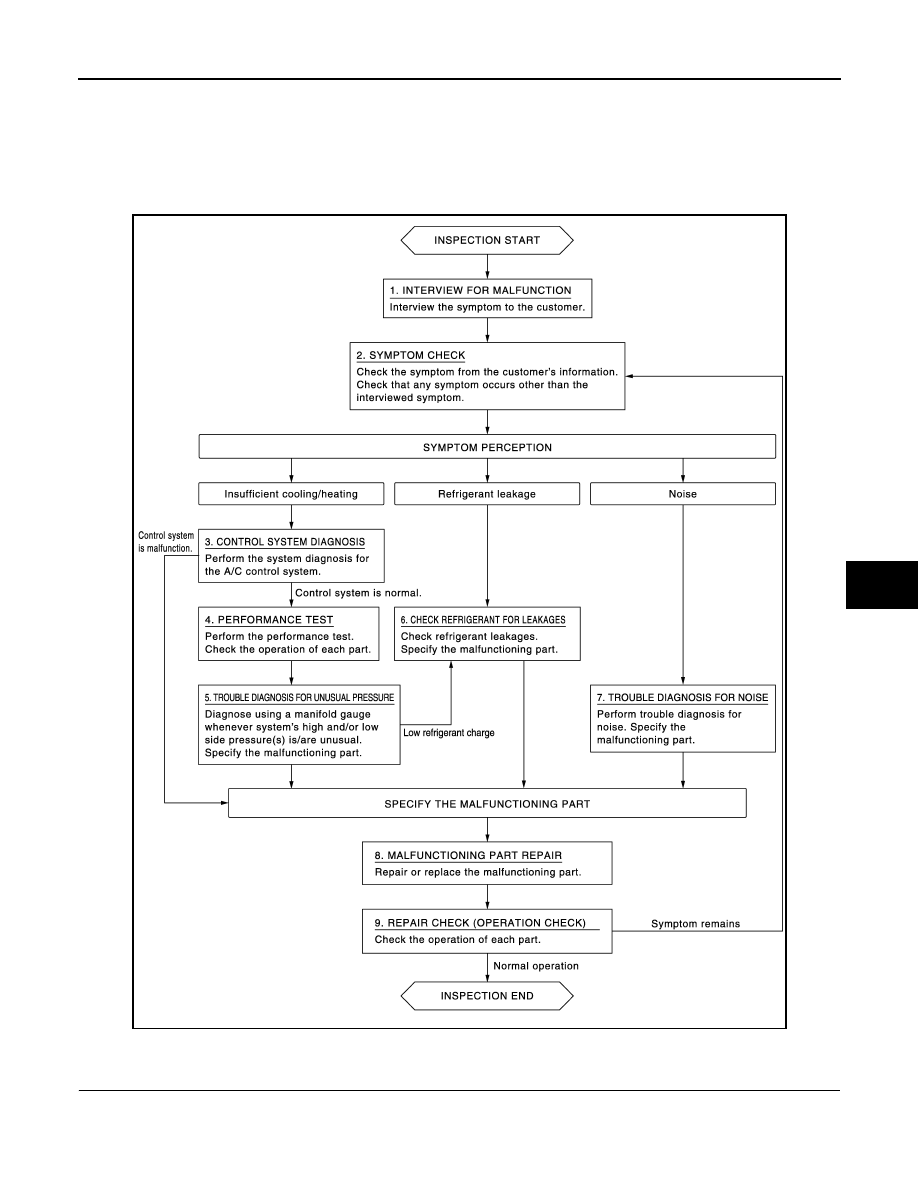
DIAGNOSIS AND REPAIR WORKFLOW
Work Flow
INFOID:0000000012197108
OVERALL SEQUENCE
DETAILED FLOW
1.
INTERVIEW FOR MALFUNCTION
Interview the symptom to the customer.
NNIIA0143GB