Nissan Juke F15. Manual - part 677
EM-262
< UNIT DISASSEMBLY AND ASSEMBLY >
[MR EXCEPT FOR NISMO RS MODELS]
CAMSHAFT
b. Pry at the position of the (
) in the figure to cut away the liquid
gasket, and remove the camshaft bracket.
CAUTION:
A liquid gasket more adhesive than previous types is
applied when shipped, so never force it off of a position not
specified.
6. Remove camshaft.
7. Remove valve lifter.
• Identify installation position of each valve. Arrange removed valves so that they cannot be mixed up.
8. If necessary, remove the camshaft signal plates from the camshaft.
INSTALLATION
1. Install valve lifter.
• If reused, install in the original position.
2. Install camshaft.
• Clean the journal to remove any foreign material, dust, and oil.
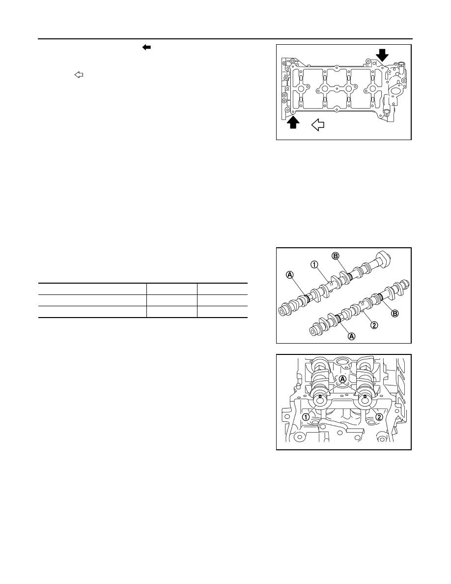
• Distinguish between the intake and the exhaust by looking at
the different shapes of the front and rear ends of the camshaft
or by using the identification colors (A) and (B).
• Install camshafts to the cylinder head so that knock pin (A) on
front end is positioned as shown in the figure.
NOTE:
The knock pin does not stop at the position facing straight up
due to the camshaft nose location. Therefore, it is generally
acceptable for the position of the knock pin to be almost at the
upper side.
3. Install camshaft bracket according to the following procedure.
a. Remove foreign material completely from the back of camshaft bracket and cylinder head mounting sur-
face.
: Engine front
JPBIA4407ZZ
Identification color
A
B
Camshaft (EXH) (1)
—
Orange
Camshaft (INT) (2)
Orange
—
JPBIA4408ZZ
1
: Camshaft (EXH)
2
: Camshaft (INT)
JPBIA4409ZZ