Nissan Juke F15. Manual - part 635


  Index      Nissan     Nissan Juke F15 (2015 year) - Service and Repair Manual


Search            


Content   ..  633  634  635  636   ..


Nissan Juke F15. Manual - part 635


EM-94

< UNIT DISASSEMBLY AND ASSEMBLY >

[MR FOR NISMO RS MODELS]

CAMSHAFT

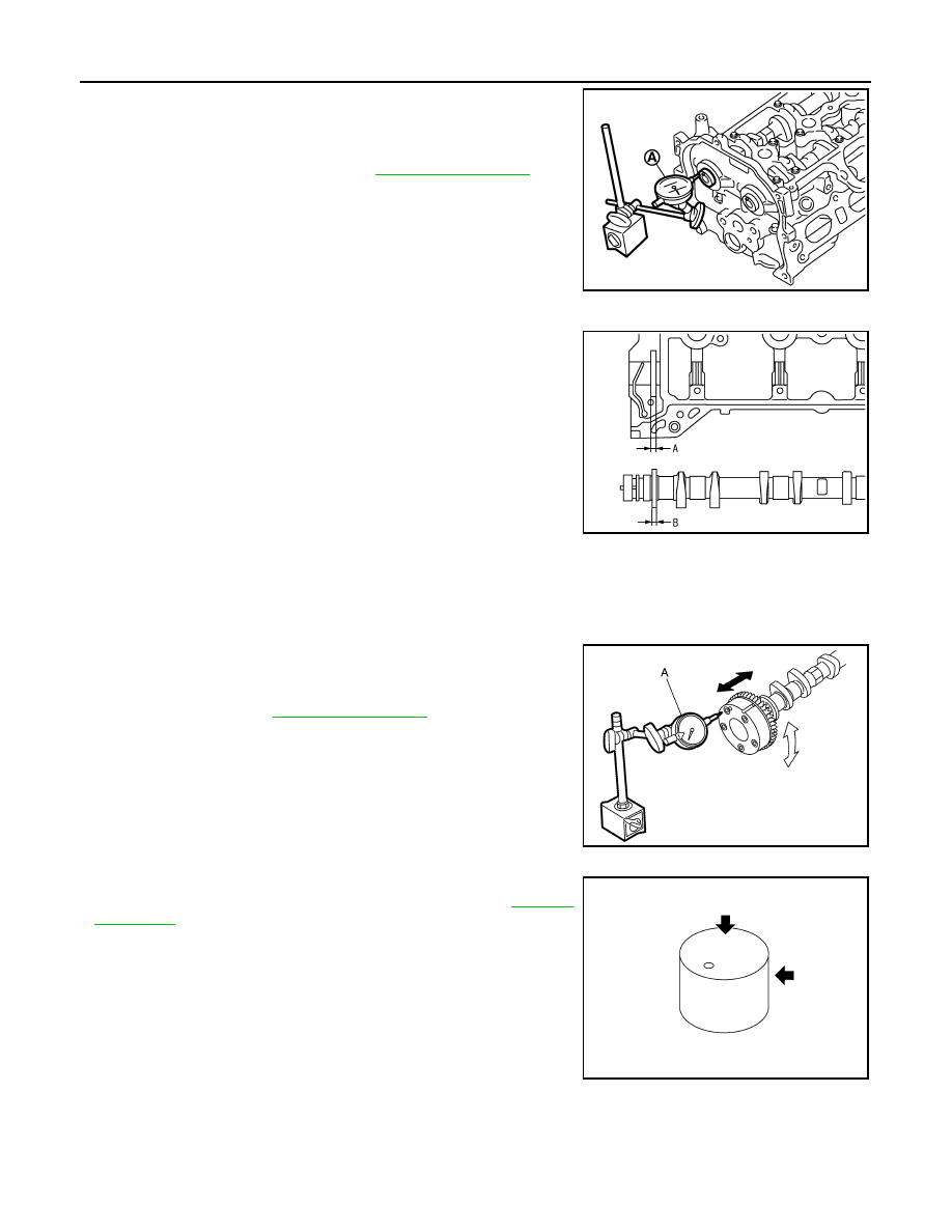
2. Install dial indicator in thrust direction on front end of camshaft.

Read the end play of dial indicator (A) when camshaft is moved

forward/backward (in direction to axis).

• Measure the following parts if out of the standard.

- Dimension (A) for groove of cylinder head No. 1 journal

- Dimension (B) for camshaft flange

• Refer to the standards above, and then replace camshaft and/

or cylinder head.

Camshaft Sprocket Runout

1. Put V-block on precise flat table, and support No. 2 and 5 journals of camshaft.

CAUTION:

Never support No. 1 journal (on the side of camshaft sprocket) because it has a different diameter

from the other four locations.

2. Measure the camshaft sprocket runout with a dial indicator (A).

(Total indicator reading)

• If it exceeds the limit, replace camshaft sprocket.

Valve Lifter 

Check if surface of valve lifter has any wear or cracks.

• If anything above is found, replace valve lifter. Refer to 

EM-140,

"Camshaft"

.

Valve Lifter Clearance

VALVE LIFTER OUTER DIAMETER

Standard and Limit : Refer to 

EM-140, "Camshaft"

.

PBIC3181J

Standard

: 4.000 - 4.030 mm (0.1575 - 0.1587 in)

Standard

: 3.877 - 3.925 mm (0.1526 - 0.1545 in)

PBIC3183J

Limit

: Refer to 

EM-140, "Camshaft"

.

JPBIA4413ZZ

KBIA0182E

CAMSHAFT

EM-95

< UNIT DISASSEMBLY AND ASSEMBLY >

[MR FOR NISMO RS MODELS]

C

D

E

F

G

H

I

J

K

L

M

A

EM

N

P

O

• Measure the outer diameter of valve lifter with a micrometer (A).

VALVE LIFTER HOLE DIAMETER

Measure the inner diameter of valve lifter hole of cylinder head with

an inside micrometer (A).

VALVE LIFTER CLEARANCE

• (Valve lifter clearance) = (Valve lifter hole diameter) – (Valve lifter

outer diameter)

• If out of the standard, referring to the each standard of valve lifter

outer diameter and valve lifter hole diameter, replace either or both

valve lifter and cylinder head.

INSPECTION AFTER INSTALLATION

Inspection of Camshaft Sprocket (INT), (EXH) Oil Groove

CAUTION:

• Perform this inspection only when DTC P0011 or P0014 is detected in self-diagnostic results of CON-

SULT and it is directed according to inspection procedure of EC section. Refer to 

EC-197, "Diagnosis

Procedure"

 (P0011) or 

EC-200, "Diagnosis Procedure"

 (P0014).

• Check when engine is cold so as to prevent burns by the splashing engine oil.
1. Check engine oil level. Refer to 

LU-9, "Inspection"

.

2. Perform the following procedure so as to prevent the engine from being unintentionally started while

checking.

a. Release the fuel pressure. Refer to 

EC-166, "Work Procedure"

.

b. Remove intake manifold. Refer to 

EM-29, "Exploded View"

.

c. Disconnect ignition coil and injector harness connectors.
d. Support the bottom surface of engine using a transmission jack, and then remove the engine mounting

bracket (RH) and engine mounting insulator (RH). Refer to 

EM-62, "2WD : Exploded View"

 (M/T models)

or 

EM-68, "AWD : Exploded View"

 (CVT models).

3. Remove intake or exhaust valve timing control solenoid valve. Refer to 

EM-76, "Exploded View"

.

• Lift the front side of the engine with a jack base to remove intake or exhaust valve timing control sole-

noid valve.

4. Clean the mounting area of intake or exhaust valve timing control solenoid valve, and then insert a clean

waste with no oil adhesion into the oil hole of the cylinder head.

5. Install engine mounting insulator (RH) and engine mounting bracket (RH). (After the removal of intake or

exhaust valve timing control solenoid valve and insertion of a waste into the oil hole.)

6. Perform cranking to check that engine oil comes out from the oil hole (mounting hole of intake or exhaust

valve timing control solenoid valve) of cylinder head.

• Regarding the engine oil check, judge it by the amount of oil adhered to the wasted inserted into the oil

hole.

WARNING:

• Never insert fingers into the oil hole.

• Be careful not to touch rotating parts (drive belt, idler pulleys and crankshaft pulley, etc.).

Standard

: Refer to 

EM-140, "Camshaft"

.

PBIC3185J

Standard

: Refer to 

EM-140, "Camshaft"

.

Standard

: Refer to 

EM-140, "Camshaft"

.

PBIC3184J

EM-96

< UNIT DISASSEMBLY AND ASSEMBLY >

[MR FOR NISMO RS MODELS]

CAMSHAFT

CAUTION:

• Never perform cranking without installing the engine mounting insulator (RH) and engine mount-

ing bracket (RH).

• Prevent splashing by using a shop cloth so as to prevent the worker from injury from engine oil

and so as to prevent engine oil contamination.

• Prevent splashing by using a shop cloth so as to prevent engine oil from being splashed to

engine and vehicle. Especially, be careful not to apply engine oil to rubber parts of drive belt,

engine mounting insulator, etc. Wipe engine oil off immediately if it is splashed.

7. Perform the following inspection if engine oil does not come out from intake or exhaust valve timing con-

trol solenoid valve oil hole of the cylinder head.

• Clean oil groove between oil strainer and intake or exhaust valve timing control solenoid valve. Refer to

LU-8, "Engine Lubrication System"

 and 

LU-8, "Engine Lubrication System Schematic"

.

8. Remove components between intake valve timing control solenoid valve and camshaft sprocket (INT) or

exhaust valve control solenoid valve and camshaft sprocket (EXH), and then check each oil groove for

clogging.

• Clean oil groove if necessary. Refer to 

LU-8, "Engine Lubrication System"

 and 

LU-8, "Engine Lubrica-

tion System Schematic"

.

9. After inspection, install removed parts in the reverse order.

OIL SEAL

EM-97

< UNIT DISASSEMBLY AND ASSEMBLY >

[MR FOR NISMO RS MODELS]

C

D

E

F

G

H

I

J

K

L

M

A

EM

N

P

O

OIL SEAL

VALVE OIL SEAL
VALVE OIL SEAL : Removal and Installation

INFOID:0000000012197299

REMOVAL

1. Remove camshafts. Refer to 

EM-88, "Exploded View"

.

2. Remove valve lifters. Refer to 

EM-88, "Exploded View"

.

3. Rotate crankshaft, and set piston whose valve oil seal is to be removed to TDC. This will prevent valve

from dropping into cylinder.

CAUTION:

When rotating crankshaft, be careful to avoid scarring front cover with timing chain.

4. Remove valve collet. 

• Compress valve spring with the valve spring compressor [SST:

KV10116200 (J-26336-A)] (A), the attachment [SST:

KV10115900 (J-26336-20)] (C), and the adapter [SST:

KV10109220 ( — )] (B). Remove valve collet with magnet

hand.

CAUTION:

• Be careful not to damage valve lifter holes.

• Fit the attachment [SST: KV10115900 (J-26336-20)] in the

center of valve spring retainer to press it.

5. Remove valve spring retainer and valve spring (with valve spring seat).

CAUTION:

Never remove valve spring seat from valve spring.

6. Remove valve oil seal with the valve oil seal puller [SST:

KV10107902 (J-38959)] (A).

INSTALLATION

1. Apply new engine oil to valve oil seal joint surface and seal lip.

JPBIA1365ZZ

1

: Valve spring retainer

A

:  Attachment

JPBIA4477ZZ

PBIC3210J


Content   ..  633  634  635  636   ..