Nissan Juke F15. Manual - part 602


  Index      Nissan     Nissan Juke F15 (2015 year) - Service and Repair Manual


Search            


Content   ..  600  601  602  603   ..


Nissan Juke F15. Manual - part 602


HO2S2 HEATER

EC-1221

< DTC/CIRCUIT DIAGNOSIS >

[MR EXCEPT FOR NISMO RS MODELS]

C

D

E

F

G

H

I

J

K

L

M

A

EC

N

P

O

HO2S2 HEATER

Component Function Check

INFOID:0000000012198750

1.

PERFORM COMPONENT FUNCTION CHECK-I

1. Start engine and warm it up to normal operating temperature.

2. Turn ignition switch OFF and wait at least 10 seconds.

3. Start engine and keep the engine speed between 3,500 and 4,000 rpm for at least 1 minute under no load.

4. Let engine idle for 1 minute.

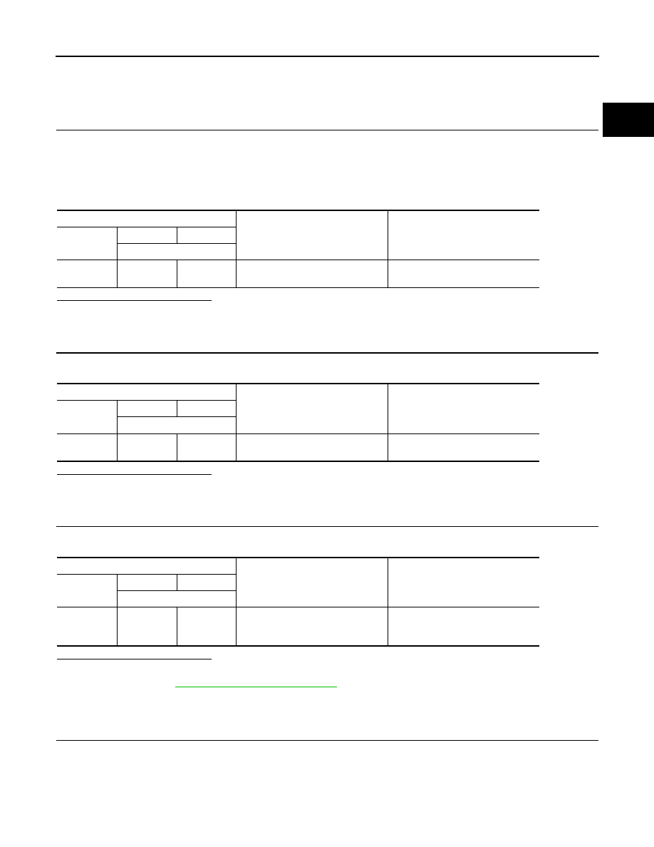
5. Check the voltage between ECM harness connector and ground as per the following condition.

Is the inspection result normal?

YES

>> INSPECTION END

NO

>> GO TO 2.

2.

PERFORM COMPONENT FUNCTION CHECK-II

Check the voltage between ECM harness connector and ground as per the following condition.

Is the inspection result normal?

YES

>> INSPECTION END

NO

>> GO TO 3.

3.

PERFORM COMPONENT FUNCTION CHECK-III

Check the voltage between ECM harness connector and ground as per the following condition.

Is the inspection result normal?

YES

>> INSPECTION END

NO

>> Proceed to 

EC-1221, "Diagnosis Procedure"

.

Diagnosis Procedure

INFOID:0000000012198751

1.

CHECK HO2S2 POWER SUPPLY CIRCUIT

1. Turn ignition switch OFF.

2. Disconnect heated oxygen sensor 2 (HO2S2) harness connector.

3. Turn ignition switch ON.

4. Check the voltage between HO2S2 harness connector and ground.

ECM

Condition

Voltage

Connector

+

Terminal

F71

84

78

Revving up to 4,000 rpm under no 
load at least 10 times

The voltage should be above 0.68 V 
at least once during this procedure.

ECM

Condition

Voltage

Connector

+

Terminal

F71

84

78

Keeping engine speed at idle for 10 
minutes

The voltage should be above 0.68 V 
at least once during this procedure.

ECM

Condition

Voltage

Connector

+

Terminal

F71

84

78

Coasting from 80 km/h (50 MPH) in 
D position (CVT), 4th gear position 
(M/T)

The voltage should be above 0.68 V 
at least once during this procedure.

EC-1222

< DTC/CIRCUIT DIAGNOSIS >

[MR EXCEPT FOR NISMO RS MODELS]

HO2S2 HEATER

Is the inspection result normal?

YES

>> GO TO 2.

NO

>> Repair or replace error-detected parts.

2.

CHECK HO2S2 OUTPUT SIGNAL CIRCUIT

1. Turn ignition switch OFF.

2. Disconnect ECM harness connector.

3. Check the continuity between HO2S2 harness connector and ECM harness connector.

4. Also check harness for short to ground and short to power.
Is the inspection result normal?

YES

>> GO TO 3.

NO

>> Repair or replace error-detected parts.

3.

CHECK HEATED OXYGEN SENSOR 2 HEATER

Check the heated oxygen sensor 2 heater. Refer to 

EC-1222, "Component Inspection"

.

Is the inspection result normal?

YES

>> Check intermittent incident. Refer to 

GI-45, "Intermittent Incident"

.

NO

>> GO TO 4.

4.

REPLACE HEATED OXYGEN SENSOR 2

Replace heated oxygen sensor 2. Refer to 

EX-5, "Exploded View"

.

CAUTION:

• Discard any sensor which has been dropped from a height of more than 0.5 m (19.7 in) onto a hard

surface such as a concrete floor; use a new one.

• Before installing new sensor, clean exhaust system threads using Oxygen Sensor Thread Cleaner

[commercial service tool (J-43897-18 or J43897-12)] and approved Anti-seize Lubricant (commercial

service tool).

>> INSPECTION END

Component Inspection

INFOID:0000000012198752

1.

CHECK HEATED OXYGEN SENSOR 2 HEATER

1. Turn ignition switch OFF.

2. Disconnect heated oxygen sensor 2 (HO2S2) harness connector.

3. Check resistance between HO2S2 terminals as per the following.

+

Voltage

HO2S2

Connector

Terminal

F71

4

Ground

Battery voltage

+

Continuity

HO2S2

ECM

Connector

Terminal

Connector

Terminal

F71

3

F24

117

Existed

+

Resistance

Heated oxygen sensor 2

Terminal

4

3

3.3 - 4.4 

Ω [at 25°C (77°F)]

HO2S2 HEATER

EC-1223

< DTC/CIRCUIT DIAGNOSIS >

[MR EXCEPT FOR NISMO RS MODELS]

C

D

E

F

G

H

I

J

K

L

M

A

EC

N

P

O

Is the inspection result normal?

YES

>> INSPECTION END

NO

>> GO TO 2.

2.

REPLACE HEATED OXYGEN SENSOR 2

Replace heated oxygen sensor 2. Refer to 

EX-5, "Exploded View"

.

CAUTION:

• Discard any sensor which has been dropped from a height of more than 0.5 m (19.7 in) onto a hard

surface such as a concrete floor; use a new one.

• Before installing new sensor, clean exhaust system threads using Oxygen Sensor Thread Cleaner

[commercial service tool (J-43897-18 or J43897-12)] and approved Anti-seize Lubricant (commercial

service tool).

>> INSPECTION END

1

2

∞ Ω

(Continuity should not exist)

3

4

2

1

4

3

+

Resistance

Heated oxygen sensor 2

Terminal

EC-1224

< DTC/CIRCUIT DIAGNOSIS >

[MR EXCEPT FOR NISMO RS MODELS]

ON BOARD REFUELING VAPOR RECOVERY (ORVR)

ON BOARD REFUELING VAPOR RECOVERY (ORVR)

Component Function Check

INFOID:0000000012198753

1.

CHECK ORVR FUNCTION

Check whether the following symptoms are present.

• Fuel odor from EVAP canister is strong.

• Cannot refuel/Fuel odor from the fuel filler opening is strong while refueling.
Is any symptom present?

YES

>> Proceed to 

EC-1224, "Diagnosis Procedure"

.

NO

>> INSPECTION END

Diagnosis Procedure

INFOID:0000000012198754

1.

INSPECTION START

Check whether the following symptoms are present.

A: Fuel odor from EVAP canister is strong.

B: Cannot refuel/Fuel odor from the fuel filler opening is strong while refueling.
Which symptom is present?

A

>> GO  TO  2.

B

>> GO  TO  8.

2.

CHECK EVAP CANISTER

1. Remove EVAP canister with EVAP canister vent control valve and EVAP control system pressure sensor

attached.

2. Weigh the EVAP canister with EVAP canister vent control valve and EVAP control system pressure sensor

attached.

The weight should be less than 1.9 kg (4.2 lb).

Is the inspection result normal?

YES

>> GO TO 3.

NO

>> GO TO 4.

3.

CHECK IF EVAP CANISTER IS SATURATED WITH WATER

Check if water will drain from EVAP canister.
Does water drain from the EVAP canister?

YES

>> GO TO 4.

NO

>> GO TO 7.

4.

REPLACE EVAP CANISTER

Replace EVAP canister with a new one.

>> GO TO 5.

5.

CHECK DRAIN FILTER

Refer to 

EC-1228, "Component Inspection (Drain filter)"

.

Is the inspection result normal?

OK

>> GO TO 6.

NO

>> Replace drain filter.

6.

DETECT MALFUNCTIONING PART

PBIB1213E


Content   ..  600  601  602  603   ..