Nissan Juke F15. Manual - part 572
P1554 BATTERY CURRENT SENSOR
EC-1101
< DTC/CIRCUIT DIAGNOSIS >
[MR EXCEPT FOR NISMO RS MODELS]
C
D
E
F
G
H
I
J
K
L
M
A
EC
N
P
O
Diagnosis Procedure
INFOID:0000000012198624
1.
CHECK BATTERY CURRENT SENSOR POWER SUPPLY
1. Turn ignition switch OFF.
2. Disconnect battery current sensor harness connector.
3. Turn ignition switch ON.
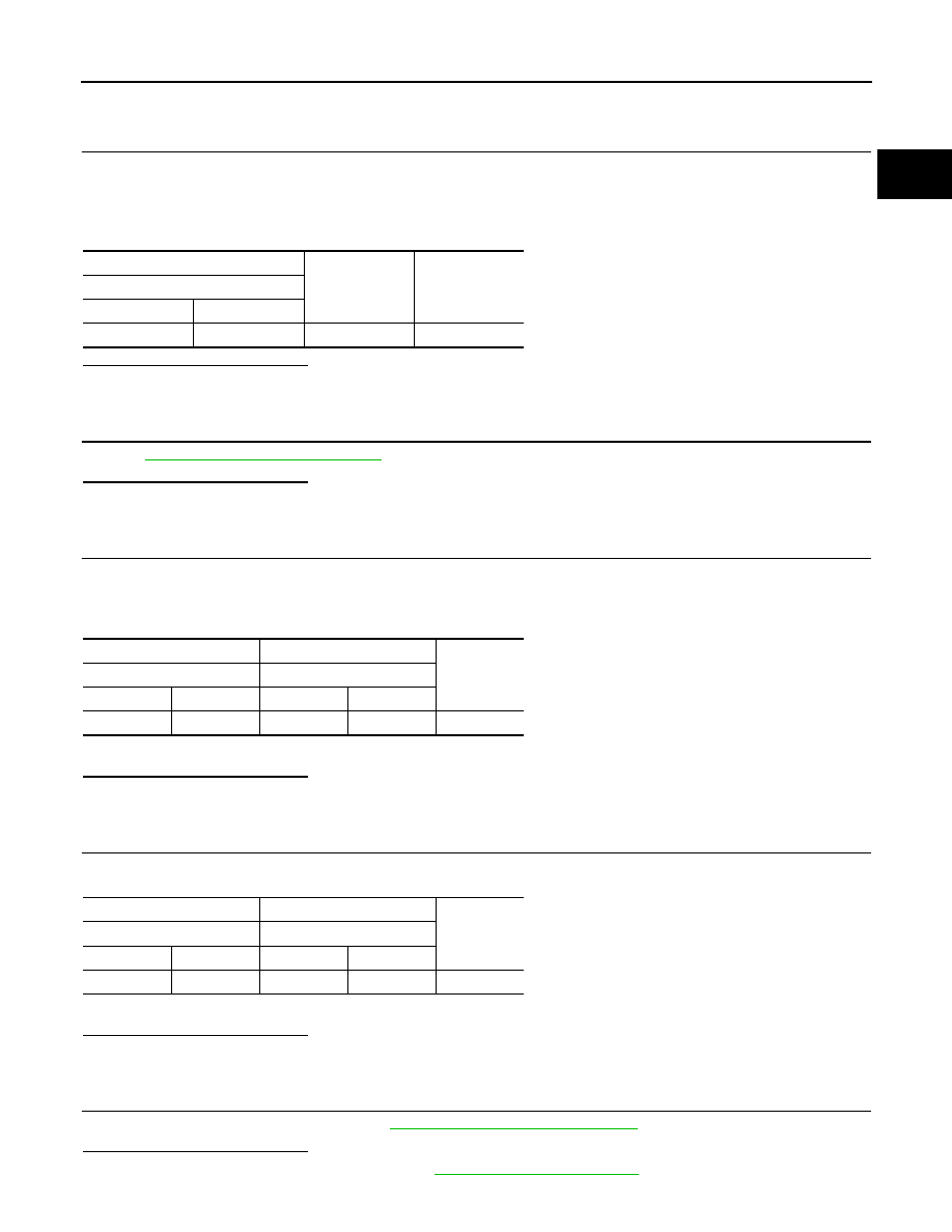
4. Check the voltage between battery current sensor harness connector and ground.
Is the inspection result normal?
YES
>> GO TO 3.
NO
>> GO TO 2.
2.
CHECK SENSOR POWER SUPPLY 2 CIRCUIT
Perform
EC-1240, "Diagnosis Procedure"
Is the inspection result normal?
YES
>> Perform the trouble diagnosis for power supply circuit.
NO
>> Repair or replace error-detected parts.
3.
CHECK BATTERY CURRENT SENSOR GROUND CIRCUIT
1. Turn ignition switch OFF.
2. Disconnect ECM harness connector.
3. Check the continuity between battery current sensor harness connector and ECM harness connector.
4. Also check harness for short to power.
Is the inspection result normal?
YES
>> GO TO 4.
NO
>> Repair or replace error-detected parts.
4.
CHECK BATTERY CURRENT SENSOR INPUT SIGNAL CIRCUIT
1. Check the continuity between battery current sensor harness connector and ECM harness connector.
2. Also check harness for short to ground and to power.
Is the inspection result normal?
YES
>> GO TO 5.
NO
>> Repair or replace error-detected parts
5.
CHECK BATTERY CURRENT SENSOR
Check the battery current sensor. Refer to
EC-1092, "Component Inspection"
Is the inspection result normal?
YES
>> Check intermittent incident. Refer to
GI-45, "Intermittent Incident"
.
+
-
Voltage
(Approx.)
Battery current sensor
Connector
Terminal
F52
1
Ground
5 V
+
−
Continuity
Battery current sensor
ECM
Connector
Terminal
Connector
Terminal
F52
3
F23
43
Existed
+
−
Continuity
Battery current sensor
ECM
Connector
Terminal
Connector
Terminal
F52
4
F23
38
Existed