Nissan Juke F15. Manual - part 471


  Index      Nissan     Nissan Juke F15 (2015 year) - Service and Repair Manual


Search            


Content   ..  469  470  471  472   ..


Nissan Juke F15. Manual - part 471


ECM

EC-697

< ECU DIAGNOSIS INFORMATION >

[MR EXCEPT FOR NISMO RS MODELS]

C

D

E

F

G

H

I

J

K

L

M

A

EC

N

P

O

112

(G)

152

(GR)

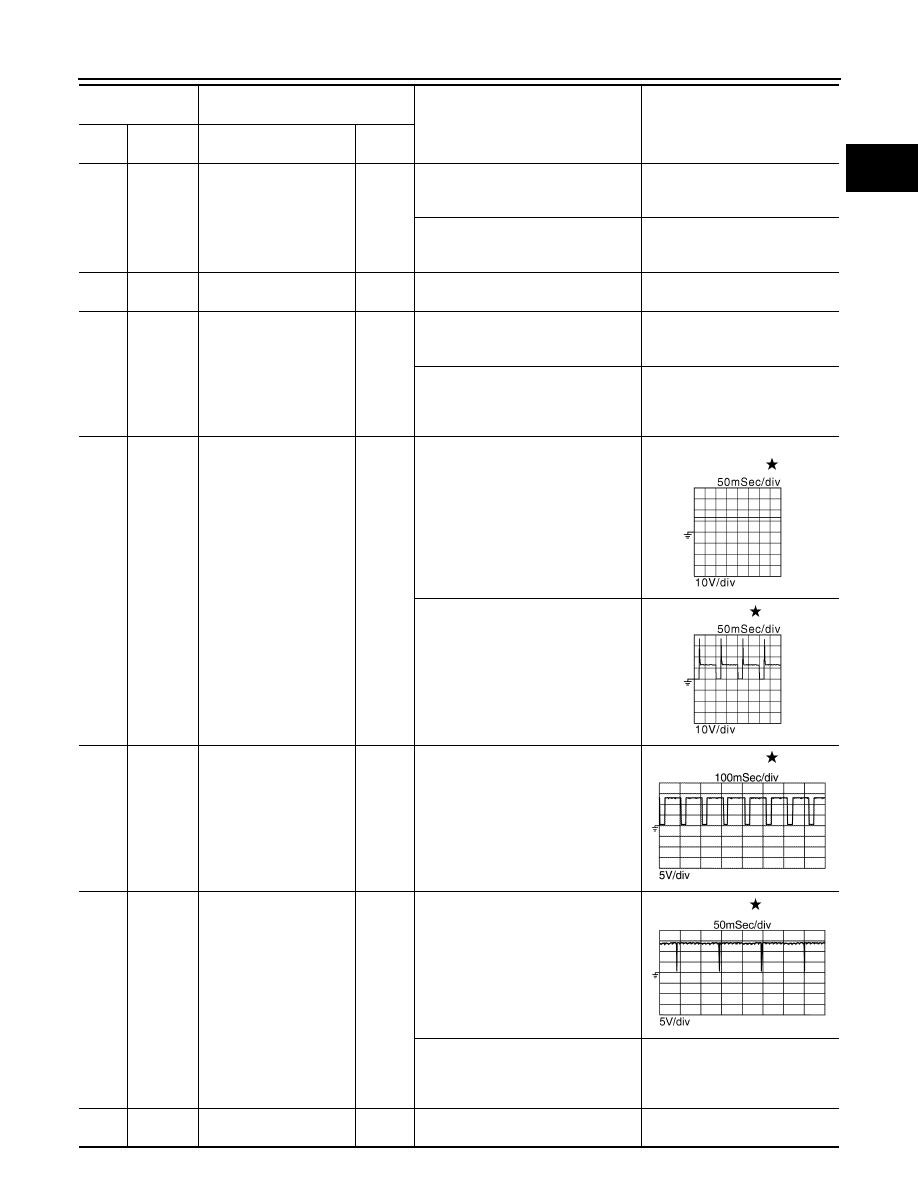
Exhaust valve timing con-
trol solenoid valve

Output

[Engine is running]
• Warm-up condition
• Idle speed

BATTERY VOLTAGE

(11 - 14 V)

[Engine is running]
• Warm-up condition
• Engine speed: 2,000 rpm

9 V

113

(Y)

152

(GR)

Power supply for ECM

Input

[Ignition switch: ON]

BATTERY VOLTAGE

(11 - 14 V)

114

(L)

152

(GR)

Intake valve timing inter-
mediate lock control sole-
noid valve

Output

[Engine is running]
• Warm-up condition
• Idle speed

BATTERY VOLTAGE

(11 - 14 V)

[Engine is running]
• Cold condition [Engine coolant tem-

perature: below 60

°C (140°F)]

• Idle speed

Battery voltage

(11 - 14 V) 

115

(L)

152

(GR)

EVAP canister purge vol-
ume control solenoid 
valve

Output

[Engine is running]
• Idle speed
• Accelerator pedal: Not depressed 

even slightly, after engine starting

BATTERY VOLTAGE

(11 - 14 V)

[Engine is running]
• Engine speed: About 2,000 rpm 

(More than 100 seconds after start-
ing engine.)

10 V

116

(G)

152

(GR)

A/F sensor 1 heater

Input

[Engine is running]
• Warm-up condition
• Idle speed

(More than 260 seconds after start-
ing engine)

2.9 - 8.8 V

117

(G)

78

(R)

Heated oxygen sensor 2 
heater

Output

[Engine is running]
• Engine speed: Below 3,600 rpm af-

ter the following conditions are met

- Engine: after warming up
- Keeping the engine speed between 

3,500 and 4,000 rpm for 1 minute 
and at idle for 1 minute under no 
load

10 V

[Ignition switch: ON]
• Engine stopped
[Engine is running]
• Engine speed: Above 3,600 rpm

BATTERY VOLTAGE

(11 - 14 V)

118

(GR)

152

(GR)

Throttle control motor 
power supply

Input

[Ignition switch: ON]

BATTERY VOLTAGE

(11 - 14 V)

Terminal No.

(Wire color)

Description

Condition

Value

(Approx.)

+

Signal name

Input/

Output

JMBIA0327GB

JMBIA0328GB

JPBIA4732ZZ

JSBIA5628ZZ

EC-698

< ECU DIAGNOSIS INFORMATION >

[MR EXCEPT FOR NISMO RS MODELS]

ECM

119

(GR)

120

(BR)

Throttle control motor 
(Open)

Output

[Ignition switch: ON]
• Engine stopped
• Selector lever: D (CVT)
• Accelerator pedal: Fully depressed

3.2 V

120

(BR)

119

(GR)

Throttle control motor 
(Close)

Output

[Ignition switch: ON]
• Engine stopped
• Selector lever: D (CVT), 1st (M/T) 
• Accelerator pedal: Fully released

1.8 V

121

(L)

148

(Y)

EVAP control system 
pressure sensor

Input

[Ignition switch: ON]

0.5 - 4.6 V

123

(P)

CAN communication line
(CAN-L)

Input/

Output

124

(L)

CAN communication line
(CAN-H)

Input/

Output

125

(G)

148

(Y)

Sensor power supply
(EVAP control system 
pressure sensor)

[Ignition switch: ON]

5 V

128

(SB)

148

(Y)

Fuel tank temperature 
sensor

Input

[Engine is running]

0 - 4.8 V

Output voltage varies with fuel 

tank temperature

132

(GR)

152

(GR)

Clutch pedal position 
switch

Input

[Ignition switch: ON]
• Clutch pedal: Fully released

0 V

[Ignition switch: ON]
• Clutch pedal: Fully depressed

BATTERY VOLTAGE

(11 - 14 V)

133

(LG)

152

(GR)

Ignition switch

Input

[Ignition switch: OFF]

0 V

[Ignition switch: ON]

BATTERY VOLTAGE

(11 - 14 V)

134

(P)

135

(B)

ASCD steering switch

Input

[Ignition switch: ON]
• ASCD steering switch: OFF

4 V

[Ignition switch: ON]
• MAIN switch: Pressed

0 V

[Ignition switch: ON]
• CANCEL switch: Pressed

1 V

[Ignition switch: ON]
• ACCEL/RES switch: Pressed

3 V

[Ignition switch: ON]
• COAST/SET switch: Pressed

2 V

135

(B)

Sensor ground
(ASCD steering switch)

139

(R)

152

(GR)

Stop lamp switch

Input

[Ignition switch: OFF]
• Brake pedal: Fully released

0 V

[Ignition switch: OFF]
• Brake pedal: Slightly depressed

BATTERY VOLTAGE

(11 - 14 V)

Terminal No.

(Wire color)

Description

Condition

Value

(Approx.)

+

Signal name

Input/

Output

JMBIA0324GB

JMBIA0326GB

ECM

EC-699

< ECU DIAGNOSIS INFORMATION >

[MR EXCEPT FOR NISMO RS MODELS]

C

D

E

F

G

H

I

J

K

L

M

A

EC

N

P

O

Fail Safe

INFOID:0000000012198247

Description

When a DTC is detected, ECM executes a mode (in the Fail-safe mode) applicable to the DTC. The fail-safe

mode has the preset traveling control mode (accelerator angle variation and engine output limit) and device fix

mode.

140

(G)

152

(GR)

Brake pedal position 
switch

Input

[Ignition switch: OFF]
• Brake pedal: Fully released

0 V

[Ignition switch: ON]
• Brake pedal: Slightly depressed

0 V

141

(L)

152

(GR)

EVAP canister vent con-
trol valve

Output

[Ignition switch: ON]

BATTERY VOLTAGE

(11 - 14 V) 

142

(O)

144

(Y)

Sensor power supply
(Accelerator pedal posi-
tion sensor 2)

[Ignition switch: ON]

5 V

143
(W)

144

(Y)

Accelerator pedal posi-
tion sensor 2

Input

[Ignition switch: ON]
• Engine stopped
• Accelerator pedal: Fully released

0.3 - 0.6 V

[Ignition switch: ON]
• Engine stopped
• Accelerator pedal: Fully depressed

1.95 - 2.1 V

144

(Y)

Sensor ground
(Accelerator pedal posi-
tion sensor 2)

145

(G)

152

(GR)

Power supply for ECM

Input

[Ignition switch: ON]

BATTERY VOLTAGE

(11 - 14 V)

146

(V)

151

(GR)

Sensor power supply
(Accelerator pedal posi-
tion sensor 1)

[Ignition switch: ON]

5 V

147

(GR)

ECM ground

148

(Y)

Sensor ground
(EVAP control system 
pressure sensor, Fuel 
tank temperature sensor)

149

(GR)

ECM ground

150

(R)

151

(GR)

Accelerator pedal posi-
tion sensor 1

Input

[Ignition switch: ON]
• Engine stopped
• Accelerator pedal: Fully released

0.6 - 0.9 V

[Ignition switch: ON]
• Engine stopped
• Accelerator pedal: Fully depressed

3.9 - 4.7 V

151

(GR)

Sensor ground
(Accelerator pedal posi-
tion sensor 1)

152

(GR)

ECM ground

Terminal No.

(Wire color)

Description

Condition

Value

(Approx.)

+

Signal name

Input/

Output

EC-700

< ECU DIAGNOSIS INFORMATION >

[MR EXCEPT FOR NISMO RS MODELS]

ECM

Fail Safe Pattern

Fail Safe List

Fail safe mode

Vehicle behavior

Traveling con-
trol mode

Accelerator an-
gle variation 
control

ECM controls the accelerator pedal depression speed to make it slower than actual speed. This 
causes a drop in accelerating performance and encourages the driver to repair malfunction.
NOTE:
ECM does not control the accelerator pedal releasing speed.

Engine output 
control

ECM reduces the engine output, according to the rise in engine speed. This reduces the vehicle 
speed to encourage the driver to repair malfunction.
• Engine output control 1: Limits the maximum speed to 120 km/h (75 MPH)*
• Engine output control 2: Limits the maximum speed to 55 km/h (34 MPH)*
*: This value is a reference value converted from engine power to vehicle speed. 
Actual power limitation value differs due to the malfunctioning part and driving condition.

Device fix mode

• This mode fixes the IVT control solenoid valve and the EVT control solenoid valve in the refer-

ence position.

• A control signals is not transmitted to EGR volume control valve and the EGR volume control 

is deactivated.

• The Intake manifold runner control valve motor is turned OFF (Intake manifold runner control 

valve opens).

Combustion 
control mode

Stratified charge 
combustion 
control at start-
ing

No stratified charge combustion at starting (cold start).

Idle speed con-
trol

Stops feedback control of idle speed and controls with specified speed.

Recovery speed 
control at decel-
erating

Stops recovery speed control by the fuel cut at decelerating and controls with specified speed.

Idle neutral con-
trol

Stops idle neutral control.

Ignition timing 
correction con-
trol

Partially controls ignition timing control.

Retardation 
control

Controls ignition timing delay control in the intermediate water temperature range.

Pattern

Fail safe mode

A

Traveling control mode

Accelerator angle variation control

B

Engine output control 1

C

Engine output control 2

D

Device fix mode

E

Combustion control mode

Stratified charge combustion control at starting

F

• Idle speed control
• Recovery speed control at decelerating
• Idle neutral control

G

• Ignition timing correction control
• Retardation control


Content   ..  469  470  471  472   ..