Nissan Juke F15. Manual - part 458
 

  Index      Nissan     Nissan Juke F15 (2015 year) - Service and Repair Manual


Search            


Content   ..  456  457  458  459   ..


Nissan Juke F15. Manual - part 458


SYSTEM

EC-645

< SYSTEM DESCRIPTION >

[MR EXCEPT FOR NISMO RS MODELS]

C

D

E

F

G

H

I

J

K

L

M

A

EC

N

P

O

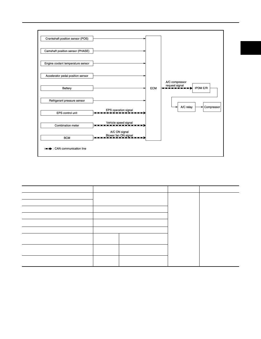
AIR CONDITIONING CUT CONTROL : System Diagram

INFOID:0000000012198218

AIR CONDITIONING CUT CONTROL : System Description

INFOID:0000000012198219

INPUT/OUTPUT SIGNAL CHART

*: ECM determines the start signal status by the signals of engine speed and battery voltage.

SYSTEM DESCRIPTION

This system improves engine operation when the air conditioner is used.

Under the following conditions, the air conditioner is turned off.

• When the accelerator pedal is fully depressed.

• When cranking the engine.

• At high engine speeds.

• When the engine coolant temperature becomes excessively high.

• When operating power steering during low engine speed or low vehicle speed.

• When engine speed is excessively low.

• When refrigerant pressure is excessively low or high.

JSBIA0320GB

Sensor

Input Signal to ECM

ECM function

Actuator

Crankshaft position sensor (POS)

Engine speed

*

Air conditioner 
cut control

IPDM E/R

Air conditioner relay

Compressor

Camshaft position sensor (PHASE)

Engine coolant temperature sensor

Engine coolant temperature

Accelerator pedal position sensor

Accelerator pedal position

Battery

Battery voltage

*

Refrigerant pressure sensor

Refrigerant pressure

EPS control unit

CAN commu-
nication

EPS operation signal

Combination meter

CAN commu-
nication

Vehicle speed signal

BCM

CAN commu-
nication

• A/C ON signal
• Blower fan ON signal

EC-646

< SYSTEM DESCRIPTION >

[MR EXCEPT FOR NISMO RS MODELS]

SYSTEM

COOLING FAN CONTROL
COOLING FAN CONTROL : System Diagram

INFOID:0000000012198220

COOLING FAN CONTROL : System Description

INFOID:0000000012198221

INPUT/OUTPUT SIGNAL CHART

*: The ECM determines the start signal status by the signals of engine speed and battery voltage.

SYSTEM DESCRIPTION

ECM controls cooling fan speed corresponding to vehicle speed, engine coolant temperature, A/C ON signal

and refrigerant pressure.

Cooling fan control signal is sent to IPDM E/R from ECM by CAN communication line. Then, IPDM E/R sends

ON/OFF pulse duty signal to cooling fan control module. Corresponding to this ON/OFF pulse duty signal,

cooling fan control module gives cooling fan motor operating voltage to cooling fan motors. Cooling fan speed

is controlled by duty cycle of cooling fan motor operating voltage sent from cooling fan control module.

JPBIA4759GB

Sensor

Input signal to ECM

ECM function

Actuator

Crankshaft position sensor (POS)

Engine speed

*

Cooling fan 
control

IPDM E/R

Cooling fan control mod-
ule

Cooling fan motor

Camshaft position sensor (PHASE)

Engine coolant temperature sensor

Engine coolant temperature

Refrigerant pressure sensor

Refrigerant pressure

Battery

Battery voltage

*

Combination meter

CAN commu-
nication

Vehicle speed signal

BCM

CAN commu-
nication

A/C ON signal

A/C evaporator temper-
ature*

Target A/C evaporator 
temperature*

Blower fan ON signal*

SYSTEM

EC-647

< SYSTEM DESCRIPTION >

[MR EXCEPT FOR NISMO RS MODELS]

C

D

E

F

G

H

I

J

K

L

M

A

EC

N

P

O

THERMAL MANAGEMENT CONTROL
THERMAL MANAGEMENT CONTROL : System Description

INFOID:0000000012198222

SYSTEM DIAGRAM

*1: For CVT models

SYSTEM DESCRIPTION

The multi-way control valve changes the paths to heater & EGR cooler, oil cooler, and radiator according to

engine coolant temperature and driving conditions.

When coolant temperature is low, the paths to heater & EGR cooler, oil cooler, and radiator are closed and

coolant is circulated only inside the engine to accelerate engine warm-up.

When coolant temperature is high, the paths to heater & EGR cooler, oil cooler, and radiator are opened and

coolant is refrigerated. This raises the coolant temperature and oil temperature rapidly and improves the fuel

economy by reducing friction among parts.

Operation

When the ignition switch is OFF, the valve is fully closed to accelerate bleeding the coolant channels.

JSBIA5422GB

EC-648

< SYSTEM DESCRIPTION >

[MR EXCEPT FOR NISMO RS MODELS]

SYSTEM

When receiving a blower fan ON signal and/or an A/C ON signal, ECM opens the flow path to the heater &

EGR cooler even when coolant temperature is low.

A: Closes all flow paths  ,  , and   and circulates coolant only inside the engine.

B: Opens the flow path to Heater & EGR cooler and circulates coolant to Heater & EGR cooler.

C: Opens the flow path to oil cooler and circulates coolant to Heater & EGR cooler and oil cooler.

D: Opens the flow path to radiator and circulates coolant to Heater & EGR cooler, oil cooler, and radiator.
E: Opens all the flow paths  ,  , and  .

The high coolant temperature control is performed by opening/closing the flow path to the radiator to raise the

engine oil temperature even when the coolant temperature is high. When engine load is high, the high coolant

temperature control is not performed because of the knocking control.

When detecting a malfunction in multi-way control valve, ECM fully opens the valve to secure cooling paths.

STARTER MOTOR DRIVE CONTROL

Valve position

Heater & EGR 

cooler

Oil cooler

Radiator

A

Full close

Full close

Full close

B

Open

Full close

Full close

C

Full open

Open

Full close

D

Full open

Full open

Open

E

Full open

Full open

Full open

JSBIA5657GB

JSBIA5434GB


Content   ..  456  457  458  459   ..