Nissan Juke F15. Manual - part 455


  Index      Nissan     Nissan Juke F15 (2015 year) - Service and Repair Manual


Search            


Content   ..  453  454  455  456   ..


Nissan Juke F15. Manual - part 455


SYSTEM

EC-633

< SYSTEM DESCRIPTION >

[MR EXCEPT FOR NISMO RS MODELS]

C

D

E

F

G

H

I

J

K

L

M

A

EC

N

P

O

“Long-term fuel trim” is overall fuel compensation carried out over time to compensate for continual deviation

of the “short-term fuel trim” from the central value. Continual deviation will occur due to individual engine differ-

ences, wear over time and changes in the usage environment.

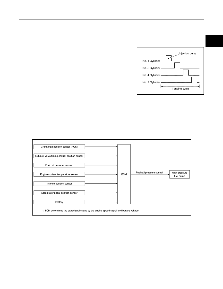
FUEL INJECTION TIMING

Sequential Direct Injection Gasoline System

Fuel is injected into each cylinder during each engine cycle accord-

ing to the ignition order.

STRATIFIED-CHARGE START CONTROL

The use of the stratified-charge combustion method enables emissions-reduction when starting the engine

with engine coolant temperature between 5

°C (41°F) and 40°C (104°F).

FUEL SHUT-OFF

Fuel to each cylinder is shut-off during deceleration, operation of the engine at excessively high speed or oper-

ation of the vehicle at excessively high speed.

FUEL PRESSURE CONTROL
FUEL PRESSURE CONTROL : System Diagram

INFOID:0000000012198203

FUEL PRESSURE CONTROL : System Description

INFOID:0000000012198204

INPUT/OUTPUT SIGNAL CHART

JPBIA4704GB

JPBIA4920GB

EC-634

< SYSTEM DESCRIPTION >

[MR EXCEPT FOR NISMO RS MODELS]

SYSTEM

*: ECM determines the start signal status by the engine speed signal and battery voltage.

System Description

Low fuel pressure control

• The low fuel pressure pump is controlled by ECM. The pumped fuel passes through the fuel filter and is sent

to the high pressure fuel pump.

• Low fuel pressure is adjusted by the fuel pressure regulator.

High fuel pressure control

The high pressure fuel pump raises the pressure of the fuel sent from the low pressure fuel pump. Actuated by

the exhaust camshaft, the high pressure fuel pump activates the high pressure fuel pump solenoid based on a

signal received from ECM, and adjusts the amount of discharge by changing the timing of closing the inlet

check valve to control fuel rail pressure.

ENGINE OIL PRESSURE CONTROL SYSTEM

Sensor

Input signal to ECM

ECM function

Actuator

Crankshaft position sensor (POS)

Engine speed

*

Fuel rail pres-
sure control

High pressure fuel pump

Exhaust valve timing control position sensor

Camshaft position

Fuel rail pressure sensor

Fuel rail pressure 

Engine coolant temperature sensor

Engine coolant temperature

Throttle position sensor

Throttle position

Accelerator pedal position sensor

Accelerator pedal position

Battery

Battery voltage

*

JPBIA4706GB

SYSTEM

EC-635

< SYSTEM DESCRIPTION >

[MR EXCEPT FOR NISMO RS MODELS]

C

D

E

F

G

H

I

J

K

L

M

A

EC

N

P

O

ENGINE OIL PRESSURE CONTROL SYSTEM : System Description

INFOID:0000000012198205

SYSTEM DIAGRAM

SYSTEM DESCRIPTION

ECM performs the variable hydraulic control (low oil pressure control and high oil pressure control) based on

signals from each sensor according to oil temperature and engine load. ECM activates the engine oil pressure

control solenoid valve and switches to the low oil pressure control and high oil pressure control. ECM uses the

low oil pressure control for 80-90 % of the operating area to maintain low oil pressure and stops piston cooling

jet (i.e. achievement of less than or equal to jet injection valve opening pressure).

High oil pressure control start condition

• High oil pressure control start condition

• High engine speed

• Coolant temperature is 60

°C (140°F)or more under high engine load condition

Low oil pressure control start condition

• Coolant temperature is less than 60

°C (140°F) under low engine speed condition

• Coolant temperature is 60

°C (140°F) or more under low engine load and low engine speed conditions

ELECTRIC IGNITION SYSTEM

JSBIA5493GB

EC-636

< SYSTEM DESCRIPTION >

[MR EXCEPT FOR NISMO RS MODELS]

SYSTEM

ELECTRIC IGNITION SYSTEM : System Diagram

INFOID:0000000012198206

ELECTRIC IGNITION SYSTEM : System Description

INFOID:0000000012198207

INPUT/OUTPUT SIGNAL CHART

*1: CVT models
*2: M/T models
*3: ECM determines the start signal status by the signals of engine speed and battery voltage.

SYSTEM DESCRIPTION

Firing order: 1 - 3 - 4 - 2 

JPBIA4921GB

Sensor

Input Signal to ECM

ECM func-

tion

Actuator

Crankshaft position sensor (POS)

Engine speed

*3

Piston position

Ignition tim-
ing control

Ignition coil (with power tran-
sistor)

Camshaft position sensor (PHASE)

Mass air flow sensor

Amount of intake air

Engine coolant temperature sensor

Engine coolant temperature

Throttle position sensor

Throttle position

Accelerator pedal position sensor

Accelerator pedal position

Turbocharger boost sensor

Turbocharger boost 

Intake air temperature sensor 2

Intake air temperature

Transmission range switch

*1

Gear position

Park/neutral position (PNP) switch

*2

Battery

Battery voltage

*3

Knock sensor

Engine knocking condition

Combination meter

CAN commu-
nication

Vehicle speed signal


Content   ..  453  454  455  456   ..