Nissan Juke F15. Manual - part 452


  Index      Nissan     Nissan Juke F15 (2015 year) - Service and Repair Manual


Search            


Content   ..  450  451  452  453   ..


Nissan Juke F15. Manual - part 452


STRUCTURE AND OPERATION

EC-621

< SYSTEM DESCRIPTION >

[MR EXCEPT FOR NISMO RS MODELS]

C

D

E

F

G

H

I

J

K

L

M

A

EC

N

P

O

STRUCTURE AND OPERATION

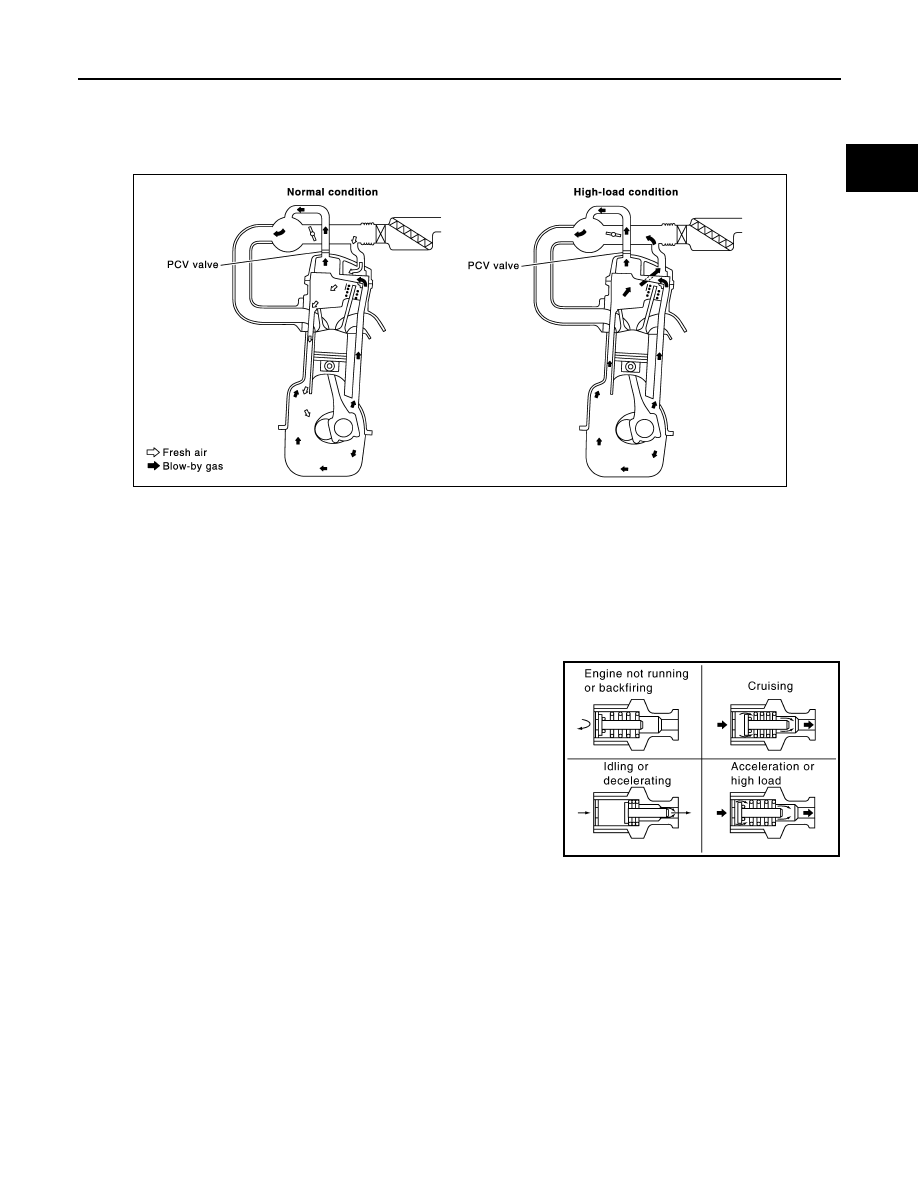
Positive Crankcase Ventilation

INFOID:0000000012198195

This system returns blow-by gas to the intake manifold.

The positive crankcase ventilation (PCV) valve is provided to conduct crankcase blow-by gas to the intake

manifold.

During partial throttle operation of the engine, the intake manifold sucks the blow-by gas through the PCV

valve.

Normally, the capacity of the valve is sufficient to handle any blow-by and a small amount of ventilating air.

The ventilating air is then drawn from the air inlet tubes into the crankcase. In this process the air passes

through the hose connecting air inlet tubes to rocker cover.

Under full-throttle condition, the manifold vacuum is insufficient to draw the blow-by flow through the valve.

The flow goes through the hose connection in the reverse direction.

On vehicles with an excessively high blow-by, the valve does not

meet the requirement. This is because some of the flow will go

through the hose connection to the air inlet tubes under all condi-

tions.

PBIB0492E

PBIB1588E

EC-622

< SYSTEM DESCRIPTION >

[MR EXCEPT FOR NISMO RS MODELS]

STRUCTURE AND OPERATION

On Board Refueling Vapor Recovery (ORVR)

INFOID:0000000012198196

From the beginning of refueling, the air and vapor inside the fuel tank go through refueling EVAP vapor cut

valve and EVAP/ORVR line to the EVAP canister. The vapor is absorbed by the EVAP canister and the air is

released to the atmosphere.

When the refueling has reached the full level of the fuel tank, the refueling EVAP vapor cut valve is closed and

refueling is stopped because of auto shut-off. The vapor which was absorbed by the EVAP canister is purged

during driving.

WARNING:

When conducting inspections below, be sure to observe the following:

• Put a “CAUTION: FLAMMABLE” sign in workshop.

• Do not smoke while servicing fuel system. Keep open flames and sparks away from work area.

• Be sure to furnish the workshop with a CO

2

 fire extinguisher.

CAUTION:

• Before removing fuel line parts, carry out the following procedures:

- Put drained fuel in an explosion-proof container and put lid on securely.

- Release fuel pressure from fuel line. Refer to 

EC-1252, "Inspection"

.

- Disconnect battery ground cable.

• Always replace O-ring when the fuel gauge retainer is removed.

• Do not kink or twist hose and tube when they are installed.

• Do not tighten hose and clamps excessively to avoid damaging hoses.

• After installation, run engine and check for fuel leaks at connection.

• Do not attempt to top off the fuel tank after the fuel pump nozzle shuts off automatically.

Continued refueling may cause fuel overflow, resulting in fuel spray and possibly a fire.

JMBIA1930GB

SYSTEM

EC-623

< SYSTEM DESCRIPTION >

[MR EXCEPT FOR NISMO RS MODELS]

C

D

E

F

G

H

I

J

K

L

M

A

EC

N

P

O

SYSTEM

ENGINE CONTROL SYSTEM
ENGINE CONTROL SYSTEM : System Diagram

INFOID:0000000012198197

ENGINE CONTROL SYSTEM : System Description

INFOID:0000000012198198

ECM controls the engine by various functions.

JSBIA7177GB

EC-624

< SYSTEM DESCRIPTION >

[MR EXCEPT FOR NISMO RS MODELS]

SYSTEM

ENGINE CONTROL SYSTEM : Integrated Engine Control

INFOID:0000000012198199

SYSTEM DESCRIPTION

ECM calculates the target intake air amount and the target boost pressure according to the effective volume of

cylinder, operation rate of EGR, and boost pressure to achieve driving condition requested by the driver. ECM

properly combines the intake and exhaust air VTC, EGR valve, throttle valve, and turbocharger bypass control

valve based on the calculations.

Function

Reference

Engine oil pressure control

EC-635, "ENGINE OIL PRESSURE CONTROL SYSTEM : Sys-
tem Description"

EGR system

EC-637, "EGR SYSTEM : System Description"

Intake manifold runner control

EC-643, "INTAKE MANIFOLD RUNNER CONTROL : System De-
scription"

Thermal management control

EC-647, "THERMAL MANAGEMENT CONTROL : System De-
scription"

Fuel injection control

EC-630, "DIRECT INJECTION GASOLINE SYSTEM : System De-
scription"

Fuel pressure control

EC-633, "FUEL PRESSURE CONTROL : System Description"

Electric ignition control

EC-636, "ELECTRIC IGNITION SYSTEM : System Description"

Intake valve timing control

EC-639, "INTAKE VALVE TIMING CONTROL : System Descrip-
tion"

Exhaust valve timing control

EC-642, "EXHAUST VALVE TIMING CONTROL : System De-
scription"

Turbocharger boost control

EC-643, "TURBOCHARGER BOOST CONTROL : System De-
scription"

Engine protection control (Low engine oil pressure)

EC-644, "ENGINE PROTECTION CONTROL AT LOW ENGINE 
OIL PRESSURE : System Description"

Air conditioning cut control

EC-645, "AIR CONDITIONING CUT CONTROL : System Descrip-
tion"

Cooling fan control

EC-646, "COOLING FAN CONTROL : System Description"

Starter motor drive control

EC-649, "STARTER MOTOR DRIVE CONTROL : System De-
scription"

Evaporative emission

EC-650, "EVAPORATIVE EMISSION SYSTEM : System Descrip-
tion"

Alternator power generation voltage variable control system

EC-651, "ALTERNATOR POWER GENERATION VOLTAGE 
VARIABLE CONTROL SYSTEM : System Description"

Fuel filler cap warning system

EC-652, "FUEL FILLER CAP WARNING SYSTEM : System De-
scription"

ASCD (Automatic speed control device)

EC-653, "AUTOMATIC SPEED CONTROL DEVICE (ASCD) : 
System Description"

Nissan dynamic control

EC-654, "INTEGRATED CONTROL SYSTEM : System Descrip-
tion"

CAN communication

EC-655, "CAN COMMUNICATION : System Description"


Content   ..  450  451  452  453   ..