Nissan Juke F15. Manual - part 439


  Index      Nissan     Nissan Juke F15 (2015 year) - Service and Repair Manual


Search            


Content   ..  437  438  439  440   ..


Nissan Juke F15. Manual - part 439


REFRIGERANT PRESSURE SENSOR

EC-569

< DTC/CIRCUIT DIAGNOSIS >

[MR FOR NISMO RS MODELS]

C

D

E

F

G

H

I

J

K

L

M

A

EC

N

P

O

4. Also check harness for short to power.
Is the inspection result normal?

YES

>> GO TO 4.

NO

>> Repair or replace error-detected parts.

4.

CHECK REFRIGERANT PRESSURE SENSOR INPUT SIGNAL CIRCUIT

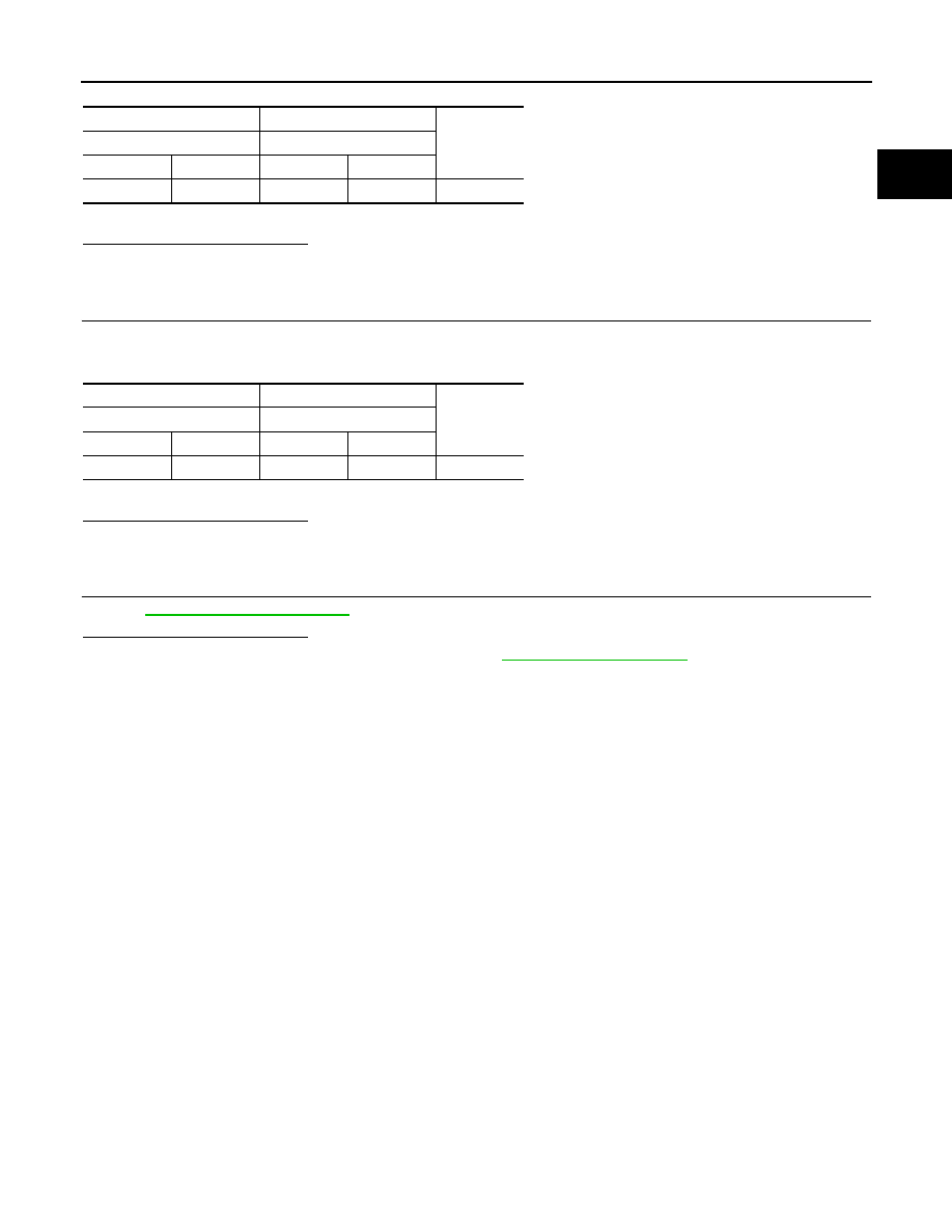
1. Check the continuity between ECM harness connector and refrigerant pressure sensor harness connec-

tor.

2. Also check harness for short to ground and to power.
Is the inspection result normal?

YES

>> GO TO 5.

NO

>> Repair or replace error-detected parts.

5.

CHECK INTERMITTENT INCIDENT.

Perfor

GI-45, "Intermittent Incident"

.

Is the inspection result normal?

YES

>> Replace refrigerant pressure sensor. Refer to 

HAC-98, "Exploded View"

.

NO

>> Repair or replace error-detected parts. 

+

Continuity

Refrigerant pressure sensor

ECM

Connector

Terminal

Connector

Terminal

E49

1

F25

12

Existed

+

Continuity

Refrigerant pressure sensor

ECM

Connector

Terminal

Connector

Terminal

E49

2

F25

19

Existed

EC-570

< DTC/CIRCUIT DIAGNOSIS >

[MR FOR NISMO RS MODELS]

BRAKE PEDAL POSITION SWITCH

BRAKE PEDAL POSITION SWITCH

Component Function Check

INFOID:0000000012198115

1.

CHECK BRAKE PEDAL POSITION SWITCH FUNCTION

With CONSULT

1. Turn ignition switch ON.

2. Select “BRAKE SW1” in “DATA MONITOR” mode of “ENGINE” using CONSULT.

3. Check “BRAKE SW1” indication as per the following conditions.

Without CONSULT

1. Turn ignition switch ON.

2. Check the voltage between ECM harness connector terminals as per the following.

Is the inspection result normal?

YES

>> INSPECTION END

NO

>> Proceed to 

EC-570, "Diagnosis Procedure"

.

Diagnosis Procedure

INFOID:0000000012198116

1.

CHECK BRAKE PEDAL POSITION SWITCH POWER SUPPLY

1. Turn ignition switch OFF.

2. Disconnect brake pedal position switch harness connector.

3. Turn ignition switch ON.

4. Check the voltage between brake pedal position switch harness connector and ground.

Is the inspection result normal?

YES

>> GO TO 2.

NO

>> Perform the trouble diagnosis for power supply circuit.

2.

CHECK BRAKE PEDAL POSITION SWITCH INPUT SIGNAL CIRCUIT

1. Turn ignition switch OFF.

2. Disconnect ECM harness connector.

3. Check the continuity between brake pedal position switch harness connector and ECM harness connec-

tor.

Monitor item

Condition

Indication

BRAKE SW1

Brake pedal

Slightly depressed

OFF

Fully released

ON

ECM

Condition

Voltage

(Approx.)

Connector

+

Terminal

E18

116

127

Brake pedal

Slightly depressed

0 V

Fully released

Battery voltage

+

Voltage

Brake pedal position switch

Connector

Terminal

E112

1

Ground

Battery voltage

+

Continuity

Brake pedal position switch

ECM

Connector

Terminal

Connector

Terminal

E112

2

E18

116

Existed

BRAKE PEDAL POSITION SWITCH

EC-571

< DTC/CIRCUIT DIAGNOSIS >

[MR FOR NISMO RS MODELS]

C

D

E

F

G

H

I

J

K

L

M

A

EC

N

P

O

4. Also check harness for short to ground and to power.
Is the inspection result normal?

YES

>> GO TO 3.

NO

>> Repair or replace error-detected parts.

3.

CHECK BRAKE PEDAL POSITION SWITCH

Check the brake pedal position switch. Refer to 

EC-571, "Component Inspection (Brake Pedal Position

Switch)"

Is the inspection result normal?

YES

>> Check intermittent incident. Refer to 

GI-45, "Intermittent Incident"

.

NO

>> Replace brake pedal position switch. Refer to 

BR-20, "Exploded View"

.

Component Inspection (Brake Pedal Position Switch)

INFOID:0000000012198117

1.

CHECK BRAKE PEDAL POSITION SWITCH-I

1. Turn ignition switch OFF.

2. Disconnect brake pedal position harness connector.

3. Check the continuity between brake pedal position switch terminals as per the following conditions.

Is the inspection result normal?

YES

>> INSPECTION END

NO

>> GO TO 2.

2.

CHECK BRAKE PEDAL POSITION SWITCH-II

1. Adjust brake pedal position switch installation. Refer to 

BR-9, "Inspection and Adjustment"

.

2. Check the continuity between brake pedal position switch terminals as per the following conditions.

Is the inspection result normal?

YES

>> INSPECTION END

NO

>> Replace brake pedal position switch. Refer to 

BR-20, "Exploded View"

.

Brake pedal position switch

Condition

Continuity

+

Terminals

1

 2

Brake pedal

Fully released

Existed

Slightly de-
pressed

Not existed

Brake pedal position switch

Condition

Continuity

+

Terminals

1

 2

Brake pedal

Fully released

Existed

Slightly de-
pressed

Not existed

EC-572

< DTC/CIRCUIT DIAGNOSIS >

[MR FOR NISMO RS MODELS]

CLUTCH PEDAL POSITION SWITCH

CLUTCH PEDAL POSITION SWITCH

Component Function Check

INFOID:0000000012198118

1.

CHECK FOR CLUTCH PEDAL POSITION SWITCH FUNCTION

1. Turn ignition switch ON.

2. Check the voltage between ECM harness connector and ground.

Is the inspection result normal?

YES

>> INSPECTION END.

NO

>> Proceed to 

EC-572, "Diagnosis Procedure"

.

Diagnosis Procedure

INFOID:0000000012198119

1.

CHECK CLUTCH PEDAL POSITION INPUT SIGNAL

1. Turn ignition switch OFF.

2. Disconnect clutch pedal position switch harness connector.

3. Turn ignition switch ON.

4. Check the voltage between clutch pedal position switch harness connector and ground.

Is the inspection result normal?

YES

>> GO TO 3.

NO

>> GO TO 2.

2.

CHECK CLUTCH PEDAL POSITION SWITCH INPUT SIGNAL CIRCUIT

1. Turn ignition switch OFF.

2. Disconnect ECM harness connectors.

3. Check the continuity between clutch pedal position switch harness connector and ECM harness connec-

tor.

4. Also check harness for short to ground and to power. 
Is the inspection result normal?

YES

>> Perform the trouble diagnosis for power supply circuit.

NO

>> Repair or replace error-detected parts.

3.

CHECK CLUTCH PEDAL POSITION SWITCH GROUND CIRCUIT

1. Turn ignition switch OFF.

2. Disconnect ECM harness connectors.

3. Check the continuity between clutch pedal position switch harness connector and ground

ECM

Condition

Voltage

(Approx.)

Connector

+

Terminal

E18

108

127

Clutch pedal

Slightly depressed

Battery voltage

Fully released

0V

+

Voltage

Clutch pedal position switch

Connector

Terminal

E113

1

Ground

Battery voltage

+

Continuity

Clutch pedal position switch

ECM

Connector

Terminal

Connector

Terminal

E113

1

E18

108

Existed


Content   ..  437  438  439  440   ..