Nissan Juke F15. Manual - part 427
P2127, P2128 APP SENSOR
EC-521
< DTC/CIRCUIT DIAGNOSIS >
[MR FOR NISMO RS MODELS]
C
D
E
F
G
H
I
J
K
L
M
A
EC
N
P
O
YES
>> GO TO 3.
NO
>> GO TO 2.
2.
CHECK SENSOR POWER SUPPLY CIRCUIT
1. Turn ignition switch OFF.
2. Disconnect ECM harness connector.
3. Check harness connector for short to power and short to ground, between the following terminals.
Is inspection result normal?
YES
>> Perform the trouble diagnosis for power supply circuit.
NO
>> Repair or replace error-detected parts.
3.
CHECK APP SENSOR 2 GROUND CIRCUIT
1. Turn ignition switch OFF.
2. Disconnect ECM harness connector.
3. Check the continuity between APP sensor harness connector and ECM harness connector.
4. Also check harness for short to power.
Is the inspection result normal?
YES
>> GO TO 4.
NO
>> Repair or replace error-detected parts.
4.
CHECK APP SENSOR 2 INPUT SIGNAL CIRCUIT
1. Check the continuity between APP sensor harness connector and ECM harness connector.
2. Also check harness for short to ground and to power.
Is the inspection result normal?
YES
>> GO TO 5.
NO
>> Repair or replace error-detected parts
5.
CHECK APP SENSOR
Check the APP sensor. Refer to
EC-522, "Component Inspection"
.
Is the inspection result normal?
YES
>> Check intermittent incident. Refer to
GI-45, "Intermittent Incident"
.
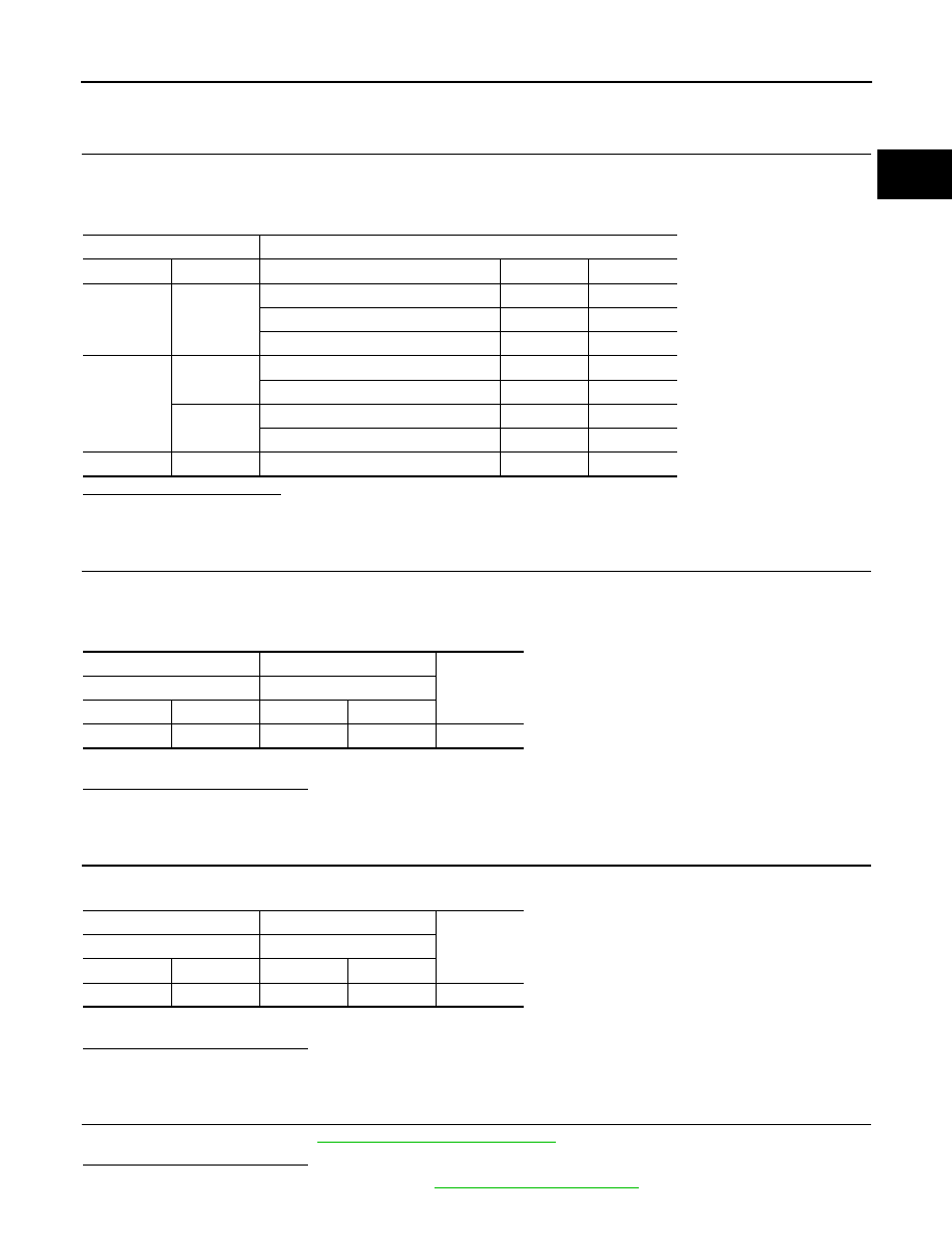
ECM
Sensor
Connector
Terminal
Name
Connector
Terminal
F25
39
FRP sensor
F5
1
EOP sensor
F43
3
Turbocharger boost sensor
F75
1
F26
68
Battery current sensor
F52
1
G sensor
B32
3
72
CMP sensor
F109
1
EVT control position sensor
F110
1
E18
118
APP sensor 2
E101
5
+
−
Continuity
APP sensor
ECM
Connector
Terminal
Connector
Terminal
E101
1
E18
120
Existed
+
−
Continuity
APP sensor
ECM
Connector
Terminal
Connector
Terminal
E101
6
E18
119
Existed