Nissan Juke F15. Manual - part 413
P1553 BATTERY CURRENT SENSOR
EC-465
< DTC/CIRCUIT DIAGNOSIS >
[MR FOR NISMO RS MODELS]
C
D
E
F
G
H
I
J
K
L
M
A
EC
N
P
O
2. Also check harness for short to ground and to power.
Is the inspection result normal?
YES
>> GO TO 5.
NO
>> Repair or replace error-detected parts
5.
CHECK BATTERY CURRENT SENSOR
Check the battery current sensor. Refer to
EC-459, "Component Inspection"
.
Is the inspection result normal?
YES
>> Check intermittent incident. Refer to
GI-45, "Intermittent Incident"
.
NO
>> Replace battery negative cable assembly. Refer to
Component Inspection
INFOID:0000000012198017
1.
CHECK BATTERY CURRENT SENSOR
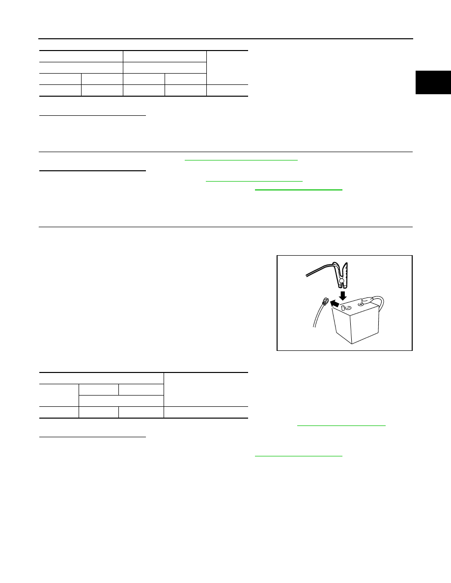
1. Turn ignition switch OFF.
2. Reconnect harness connectors disconnected.
3. Disconnect battery negative cable.
4. Install jumper cable between battery negative terminal and body
ground.
5. Turn ignition switch ON.
6. Check the voltage between ECM harness connector and
ground.
Before measuring the terminal voltage, confirm that the battery is fully charged. Refer to
PG-97, "How to Handle Battery"
.
Is the inspection result normal?
YES
>> INSPECTION END
NO
>> Replace battery negative cable assembly. Refer to
+
−
Continuity
Battery current sensor
ECM
Connector
Terminal
Connector
Terminal
F52
4
F26
80
Existed
JPBIA3286ZZ
ECM
Voltage
(Approx.)
Connector
+
-
Terminal
F26
80
87
2.5 V